Retro GEM 3DO Installation Instructions
Disclaimer: This kit is for advanced installers only. Install at your own risk. We cannot be held responsible for damage to your console and/or kit. Each kit is individually tested and confirmed working before being shipped.
Before you begin:
The kit is compatible with all models except late model mainboards that have the anvil IC.
If you are using an older GEM module make sure it is up to date using the rescue system otherwise you will get a black screen during boot. https://docs.pixelfx.co/FX-Framework-Rescue_System.html If you are using the GEM purchased with the kit then this is no concern.
The kit places a mini hdmi connector in the RF port of the console. Some JP consoles do not have an RF port hole and these will need to be cut.
If you have an existing 3DO rgb kit installed and are replacing you will need to restore any tracecuts that were performed during that installation.
Please be sure to checkout the installation videos
FZ-10 : https://www.youtube.com/watch?v=LrI2Z7xF-7k
FZ-1 : https://www.youtube.com/watch?v=_jo-eBKm4P0
**When inserting the flex make sure it is aligned all the way to the right.
Kit includes:
- 3DO Main Flex
- Female Adapter Board
- Male HDMI Adapter
- 150mm 18p FFC Cable
- Plastic Panel block with 3M tape mount
- Plastic HDMI Mount
- M1.6 Nuts (2x)
- M1.6 15mm Screw (2x)
- M1.6 6mm Screw (2x)
- M2 Nut
- M2 Screw
- 3.3V Power Board
- 3mm Thermal Pad
Items required
- Temperature Controlled Soldering Iron
- Leaded Solder
- Non-Corrosive, No Clean Flux (Amtech 559 / Kester 959T)
- 99% Isopropyl Alcohol
- Multi Meter
- 13mm step drill bit (For FZ-10 and or Goldstar?)
- 30 AWG wire
Step 0 - GEM Jumpers.
Click to expand/collapse
Set the Retro GEM Jumpers using the following link:
Step 1 - Console Disassembly and main board modifications
Click to expand/collapse
This guide will not go over the disassembly of the 3DO. Guides are available online. Once the mainboard is free remove the RF port. If your mainboard does not have an RF port then you need to desolder the two grounds where the HDMI plastic mount sits.
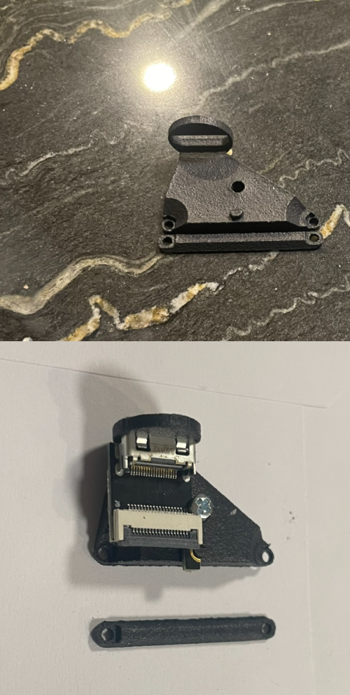
Snap the mounting bracket off the 3d printed panel by rocking back and forth. Use the M2 screw and nut to securely mount the female hdmi board as shown.
Mount bracket as shown, keeping the board as far bas as possible from the edge. A hint is to pre screw the M1.6 screw through the mount hole first. Use the shorter screws here.
Once mounted the next step is to make any case modifications if needed. Test fit the motherboard and see how alignment is. Some cosoles will need the hole just barely enlarged. A 13mm step drill bit makes perfect work of this.
FZ-1 consoles need this nub trimmed so the motherboard can sit flush.
Models that do have an rf port will need the hole drilled. This will need to be precise. The consoles that do not have the rf port do luckly have a hole cut in the inner shield. So we can mark using this to get the perfect alignment of where to drill. Some tricks to make this eaiser. Use a really small drill bit and slowly increase the size. Since we are cutting plastic, its possible to the move the holes central location but using force/angle with the drill bit.
Step 2 - Installing the Power board, main flex, controller
Click to expand/collapse
Find a good location for the 3v3 power board. The power board is semi "universal" item and can handle multiple mounting locations and oreientations. Thus some jumpers will need to be set when installing. See the pad layouts below. Make sure the check for shorts and do not hooked up backwards.
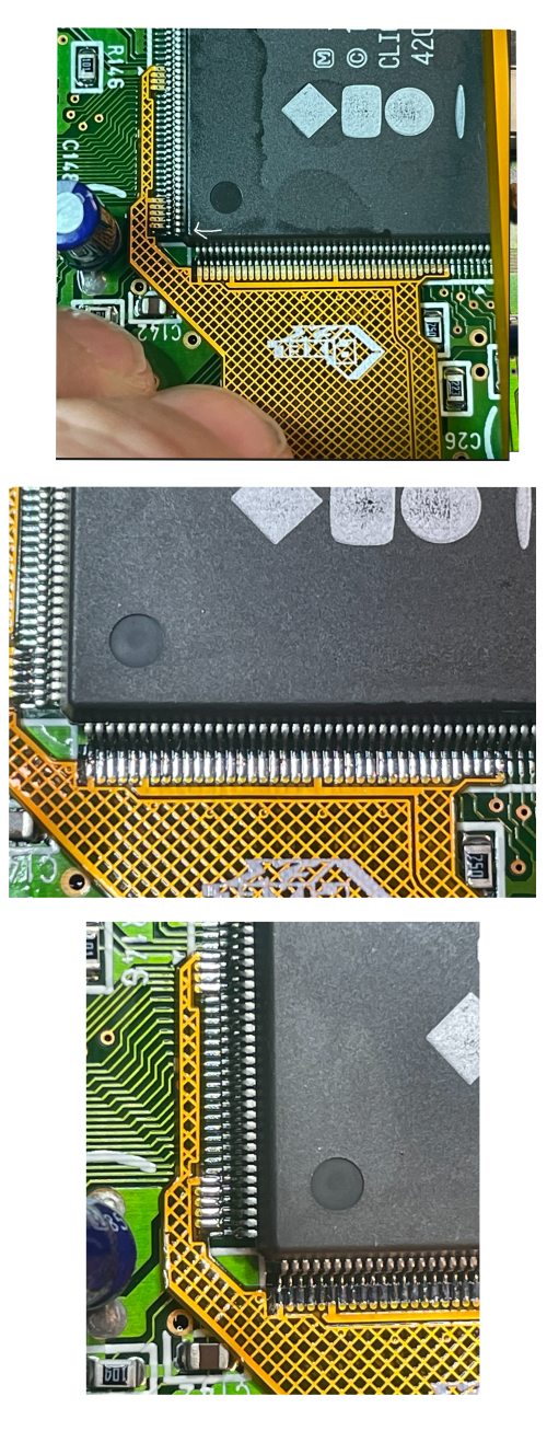
Locate the IC and mount the flex as shown. Ignore the "solder side up" this is incorrect. The flex will mount the same way in all models and variants. PAY extremely close attention to the alignment. The pads can be very "long" and its easy to be off 1 pin.
Solder the flex down.
Connect the 3v3 leg to the power board.
Connect the controllers as shown, find your board variant below.
FZ-1
FZ-10
Goldstar
Step 3 - Mounting the GEM
Click to expand/collapse
Break apart the 3d printed mount. Most consoles will need the extra thick mounting plate. The height the GEM is lifted in the mainboard is critical here. The blue thermal pad needs to make proper contact with the upper metal shield if the shield is used. If the top shield is omited than just disreguard the thermal pad. Mount the gem using the longer M2 screws. Trim the screws to length using side cutters if you are not using the extra thick spacer.Peel back the red tape and then plug in the FFC cable. Mount the gem into place. The mounting tape needs to go on top of the ARM chip. (This is relaitvely the same in all models.) Make sure the HDMI output does not come into contact with the CD-ROM mount (FZ1)
Connect the white flex cable and hdmi plug into place.
Your installation should look similar to:
FZ-1
FZ-10
Goldstar
Place the thermal pad on top. Before reassemble now is a good time to test. After confirm the installation is good, remember to confirm the thermal pad makes good contact with the metal shield during reassembly.
Step 3 - Testing and troubleshooting
Click to expand/collapse
At this point now is a good time to test the installation. Some important things to consider:-If you do not attach the CD-ROM you will get a black screen with a 3DO logo that will appear every 15 seconds. (FZ-1) -Connect a composite cable to the console and confirm it boots if you get a black screen over HDMI. -Try to open up the OSD (This will only work via the HDMI output). Left Trigger + Right Trigger + DPad Right + B over the HDMI. -What does the LED do? It should be solid during normal operation.


