N64Digital Installation Instructions
Disclaimer:
This kit is for advanced installers only. Install at your own risk. We cannot be held responsible for damage to your console and/or kit. Each kit is individually tested and confirmed working before being shipped out.
2.1.34 HW2 Firmware Issues
The launch firmware of HW2 can show a glitching output image over HDMI and RGB on some consoles and should be updated before debugging the installation!
Before you begin:
N64Digital is compatible with all N64 models/regions; with the exception of Pikachu models.
The N64Digital requires a small case cut for the mini HDMI connector. A separate company, Laser Bear, has created a no cut solution, https://laserbear.net/products/n64-digital-no-cut-mod. Please be aware that both Analog and HDMI cannot be used at the same time when using the no cut solution.
Please review the installation video. Always reference these install docs and use the video as an aid for techniques on how to preform the required steps.
https://youtu.be/LJ5PXZjXLVE
The written instructions will include both HW1 and HW2 revisons. The video only contains HW1. However the installations are almost identical.
Notible differences:
- foam block is replaced with a 3D printed piece
- clock jumper on the HW2 main board.
- Includes PIF flex vs wired install on HW1.
Kit includes:
- N64Digital PCB
- RCP Flex
- RGB Flex
- Plastic Spacer
- Foam Block (HW1)
- Plastic Block (HW2)
Items required
- Temperature Controlled Soldering Iron
- Leaded Solder
- Non Corrosive, No Clean Flux (I recommend Kester 959T)
- 99% Isopropyl Alcohol
- Multi Meter
- Miniature File Set & Exacto Knife (Cut Version)
- Kapton Tape or electrical tape
- 28 or 30 AWG wire (HW1)
- 4.5mm Gamebit Adapter
- P1 & P2 Screwdrivers
Step 1 - Console Disassembly
Click to expand/collapse
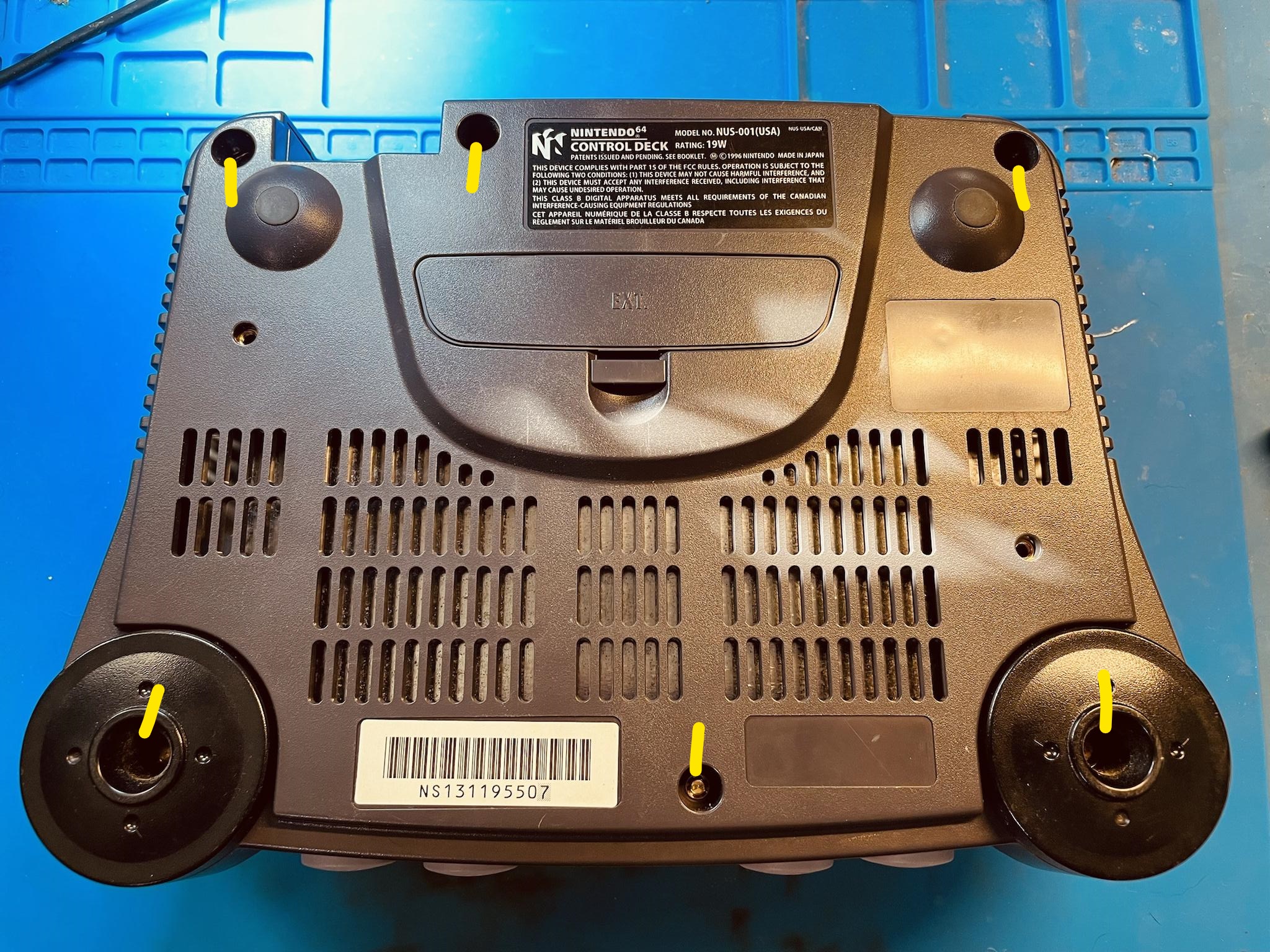
Remove all gamebit screws on the bottom of the console to remove top case.
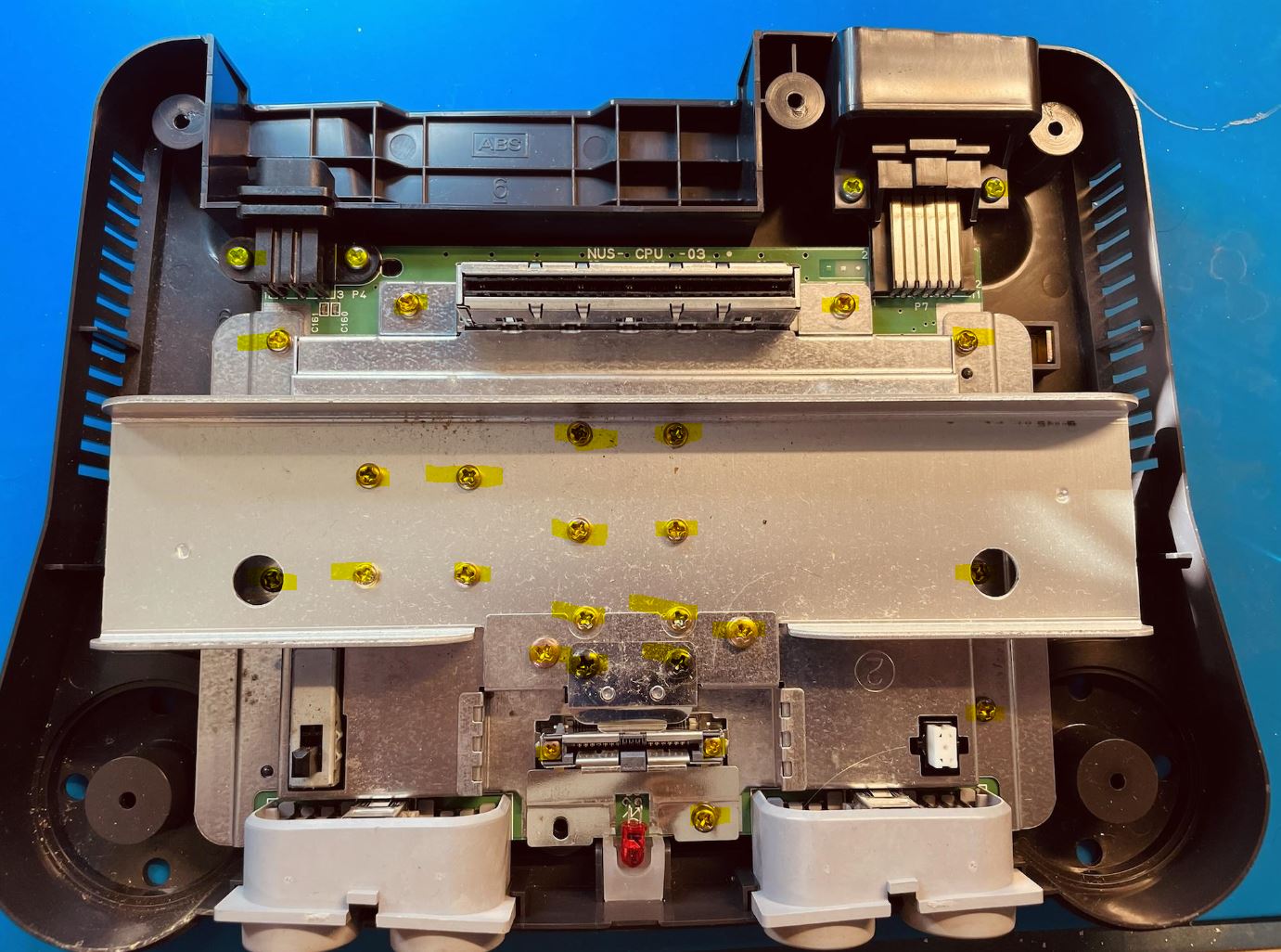
Remove all screws and remove motherboard:
Step 2 - Fitting the N64Digital PCB
If using the no cut version, skip to Step 3
Click to expand/collapse
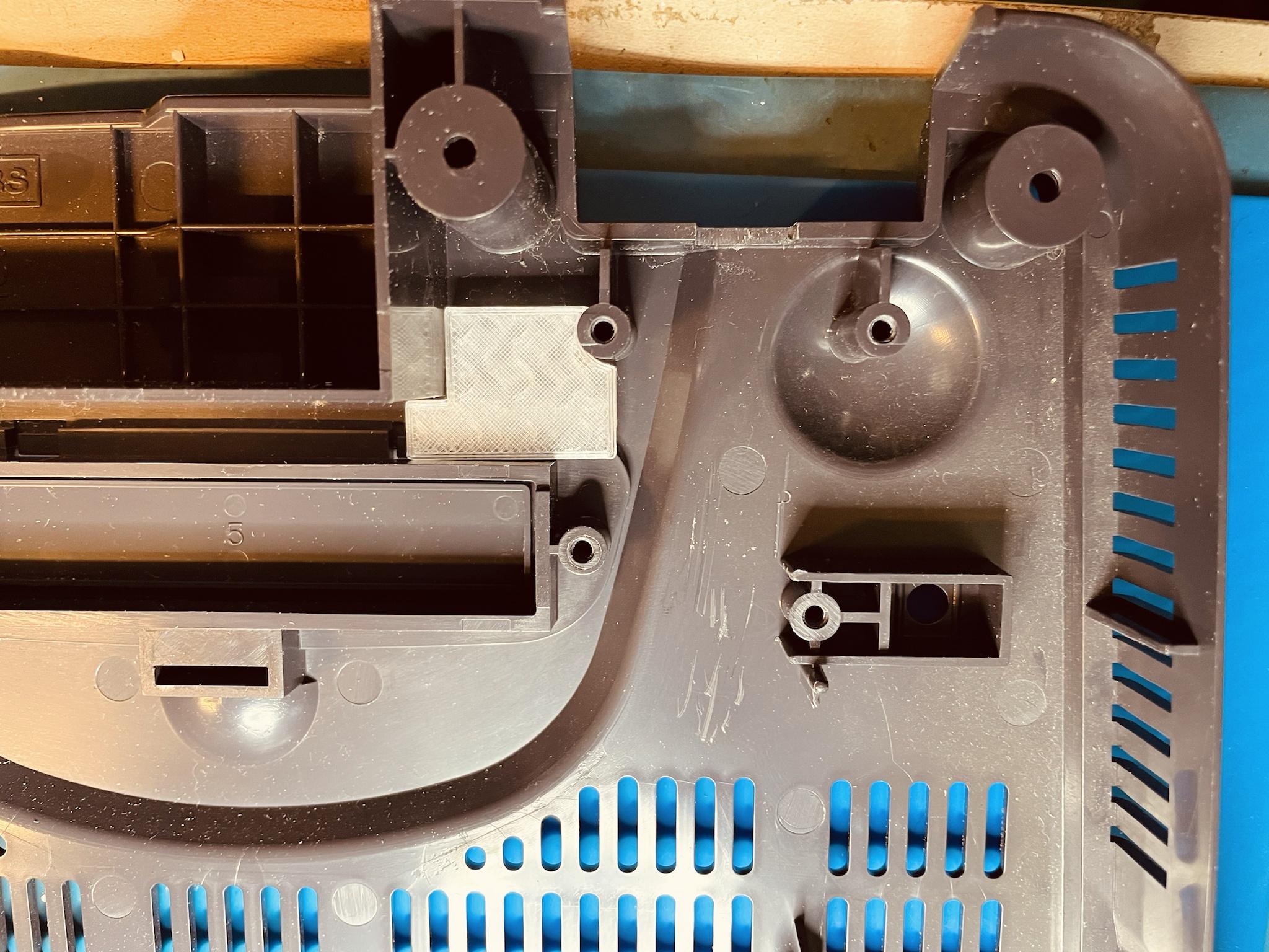
Align the N64Digtal board in the case and lightly mark the case with an exacto knife.
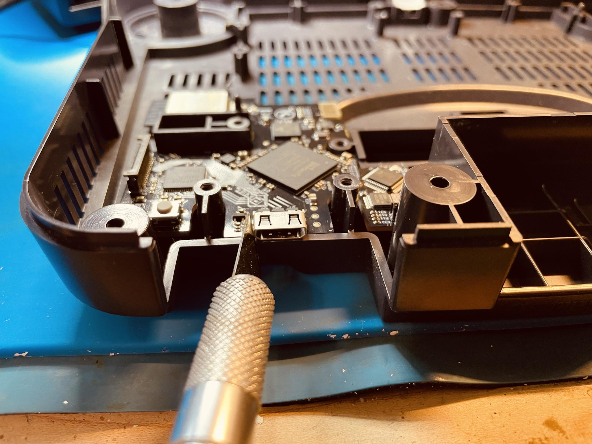
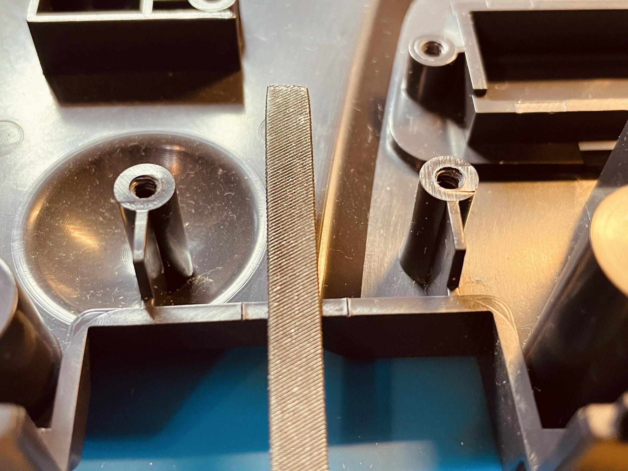
Slowly file in-between the knife marks on the case. Do this step very slow, constantly checking the fit. The Mini HDMI holds need to have a semi-tight fit. If the mod board fits too tightly, file away the burrs on the PCB from the assembly process. Refer to the installation video for more help. https://youtu.be/LJ5PXZjXLVE
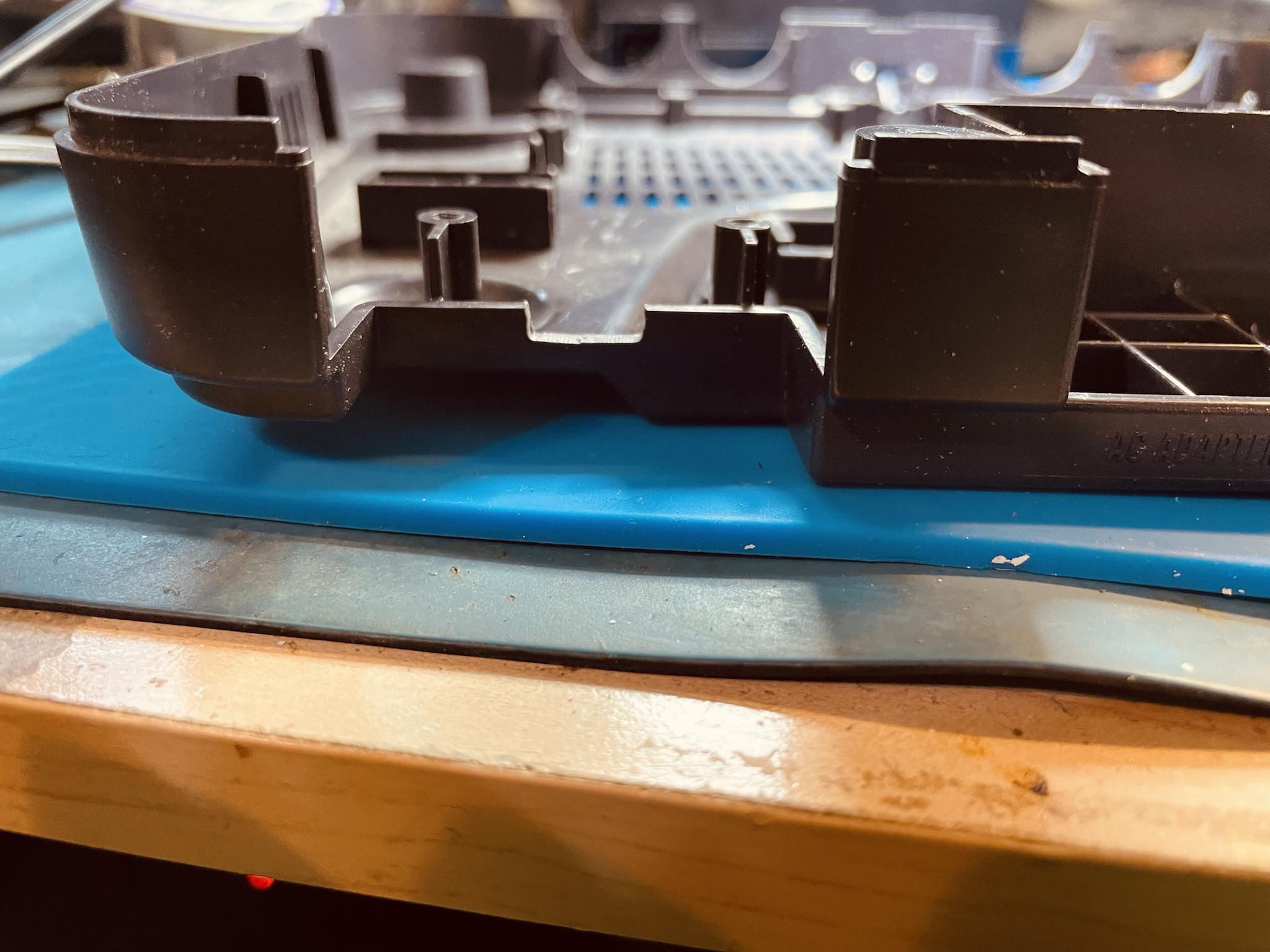
Once done filing, insert the plastic spacer followed by the board. Make sure the board sits completely flat in the N64 case.
Step 3 - Soldering the RGB Flex
If you already have an RGB mod or do not want to add RGB support - proceed to step 4
Click to expand/collapse
NUS-CPU-01, NUS-CPU-02, NUS-CPU-03 and NUS-CPU-04 motherboards needs. C22 & R14 needs to be removed.

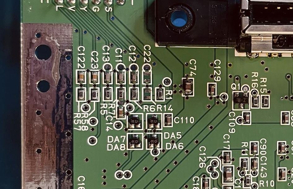
Solder the RGB Flex cable into place.
Slightly bend the RGB flex like the image below. Do not crease the flex.
Step 4 - Soldering the RCP Flex
Click to expand/collapse
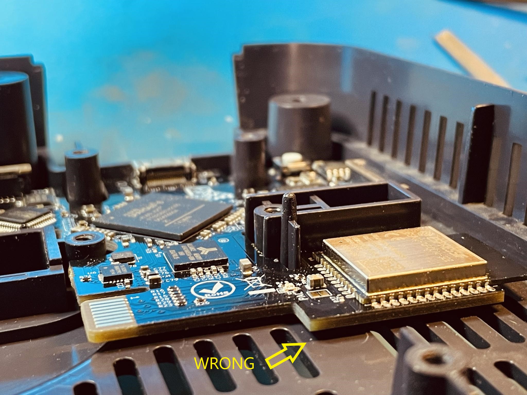
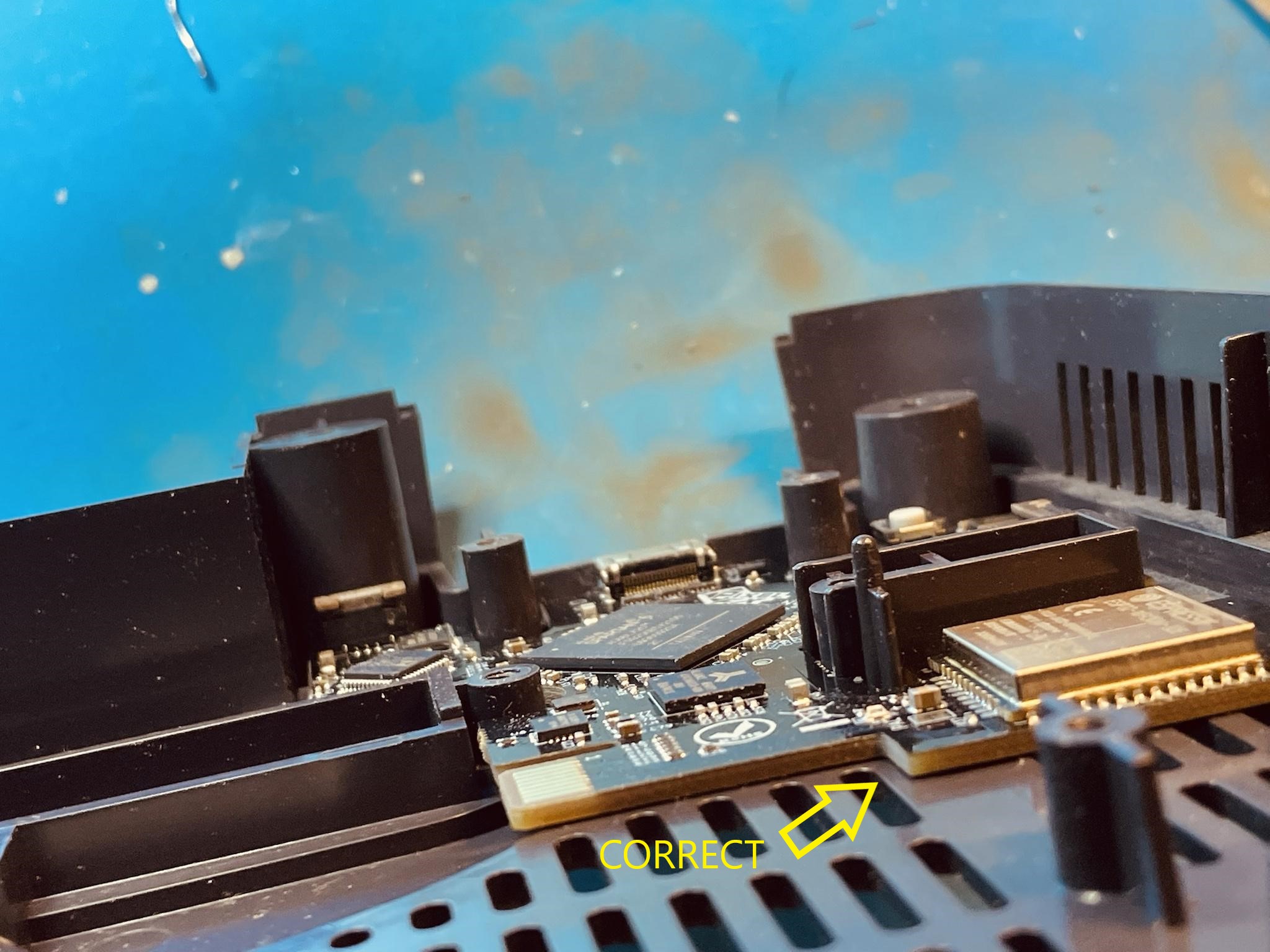
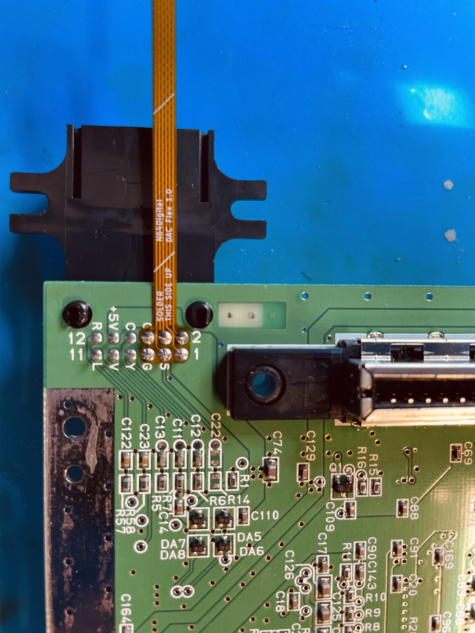
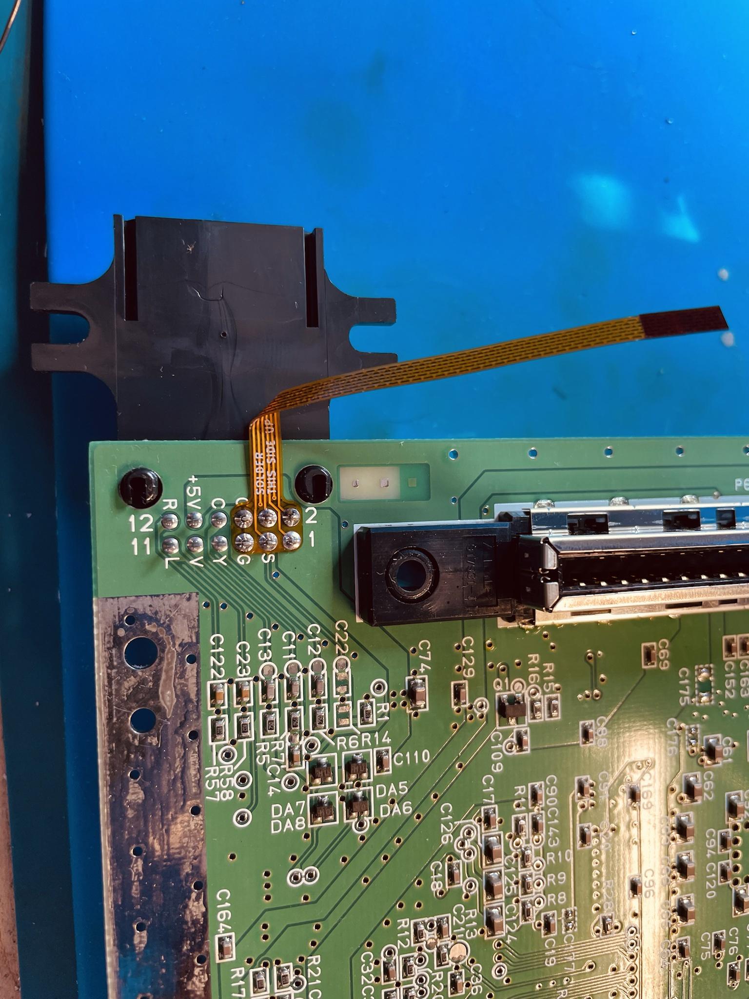
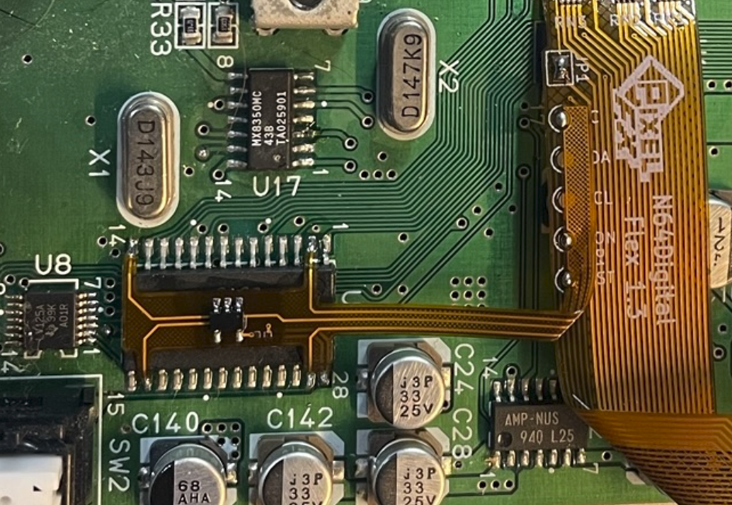
Align the flex on the RCP to pin 6.

Solder the flex cable. If this is your first time soldering a flex cable like this, please refer to the video for specific techniques. https://youtu.be/LJ5PXZjXLVE
Use a multimeter to confirm there is no continuity between adjacent pins. If a direct short is found, clear the bridge and check again.
Please click on your HW revision to show the final steps required to finish this step!
HW1
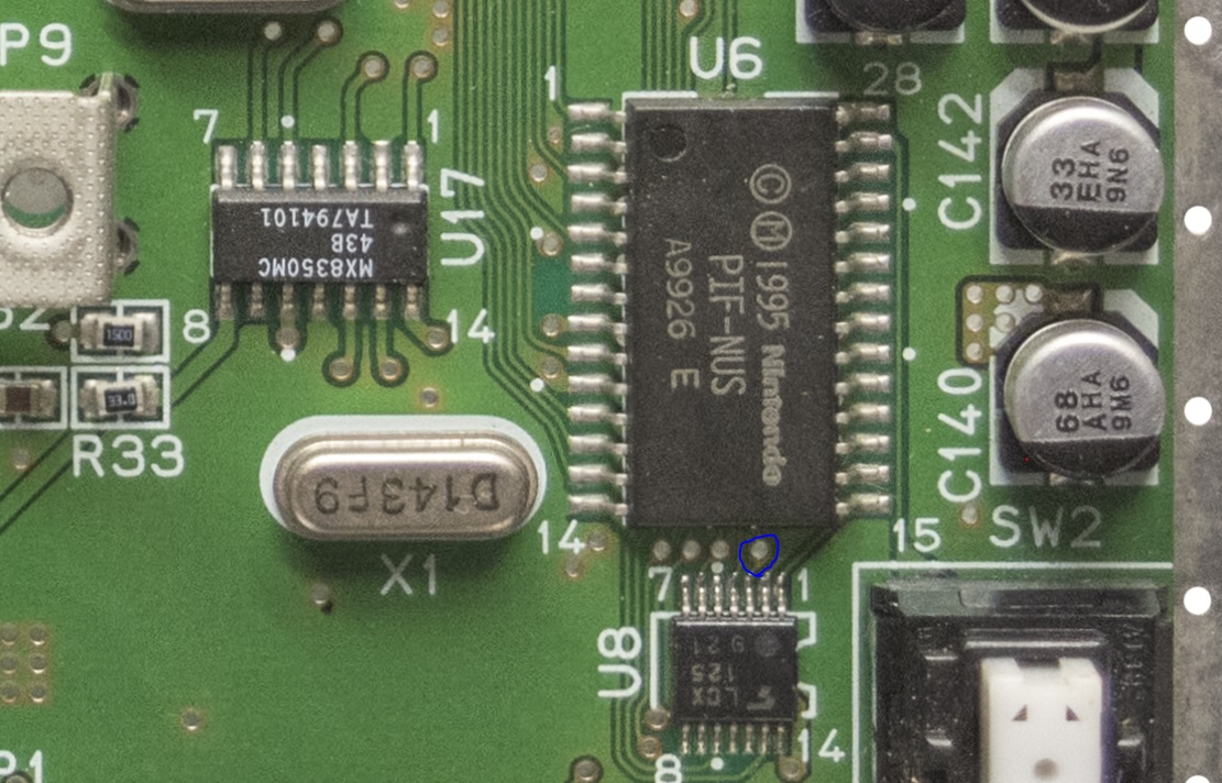
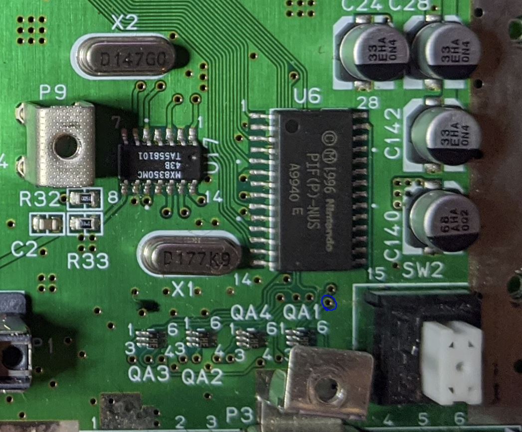
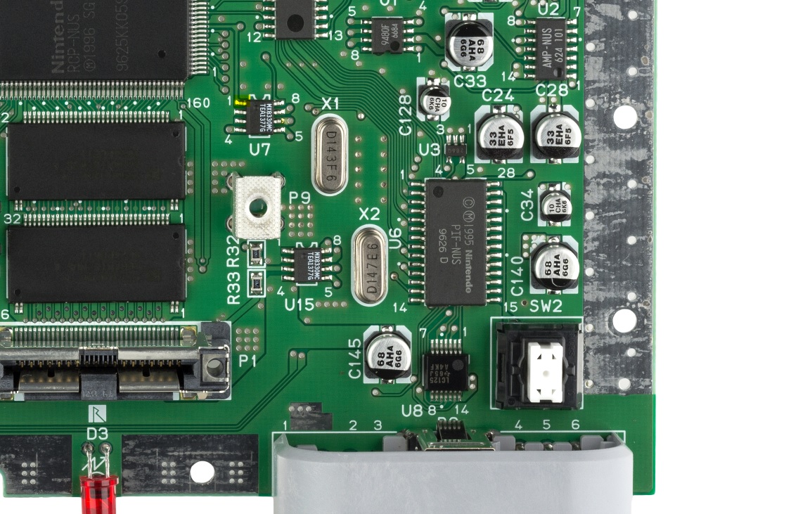
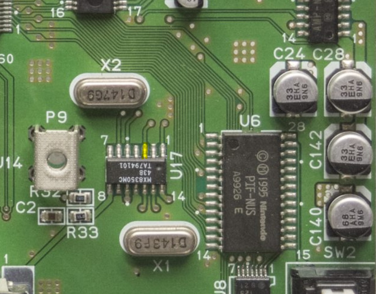
Hookup RC, RST and CON connections from the flex cable to the PIF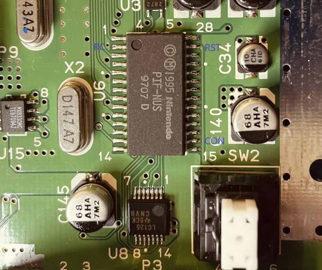
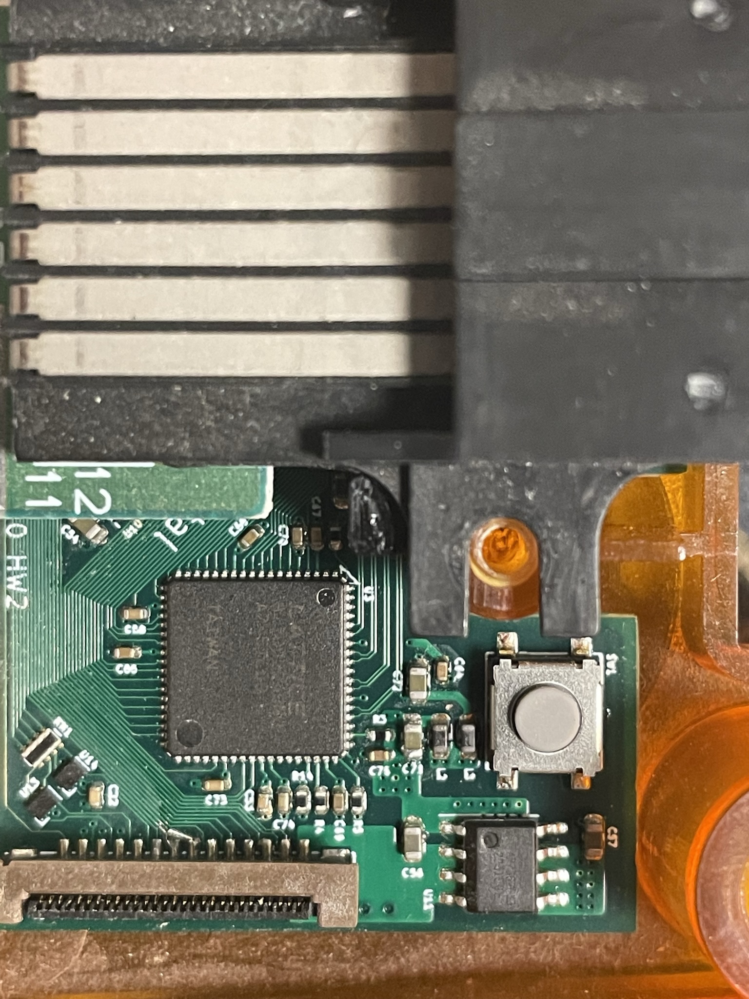
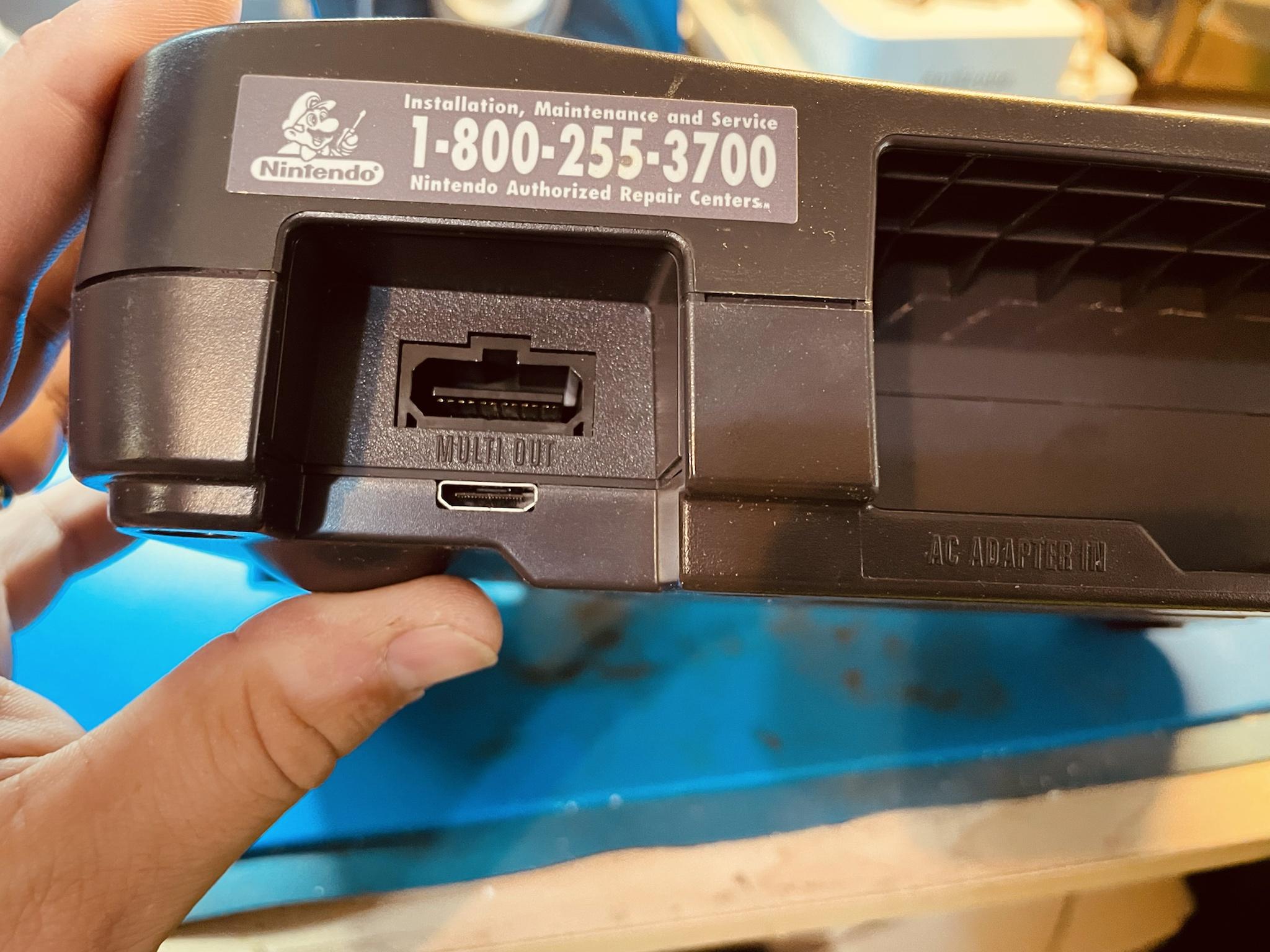
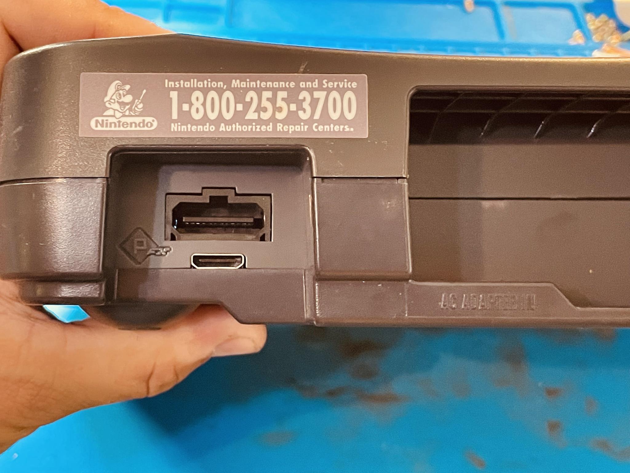
Some late model consoles require a different connection to the CON. If your console looks like the images below solder the CON wire to the via instead of PIN16 on the PIF.
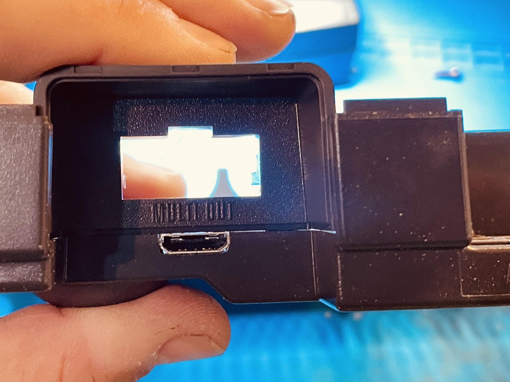
Slightly bend the RCP flex aligning it to the multiout. Refer to the image below.
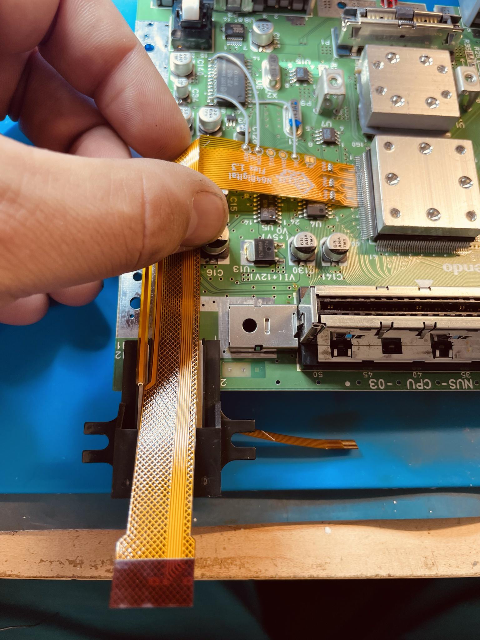
Solder the flex arm to the 5V leg. Refer to the image below.
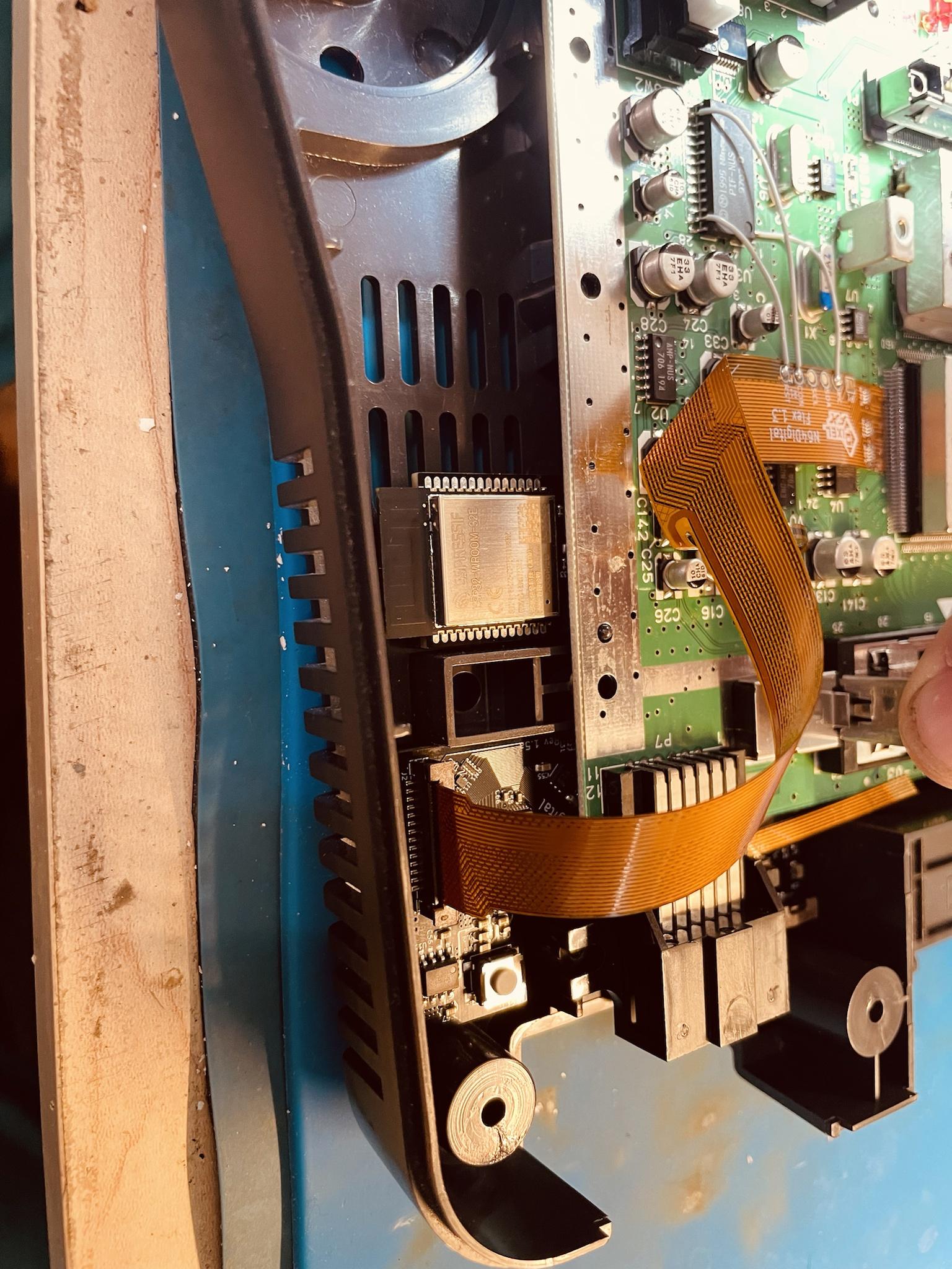
HW2
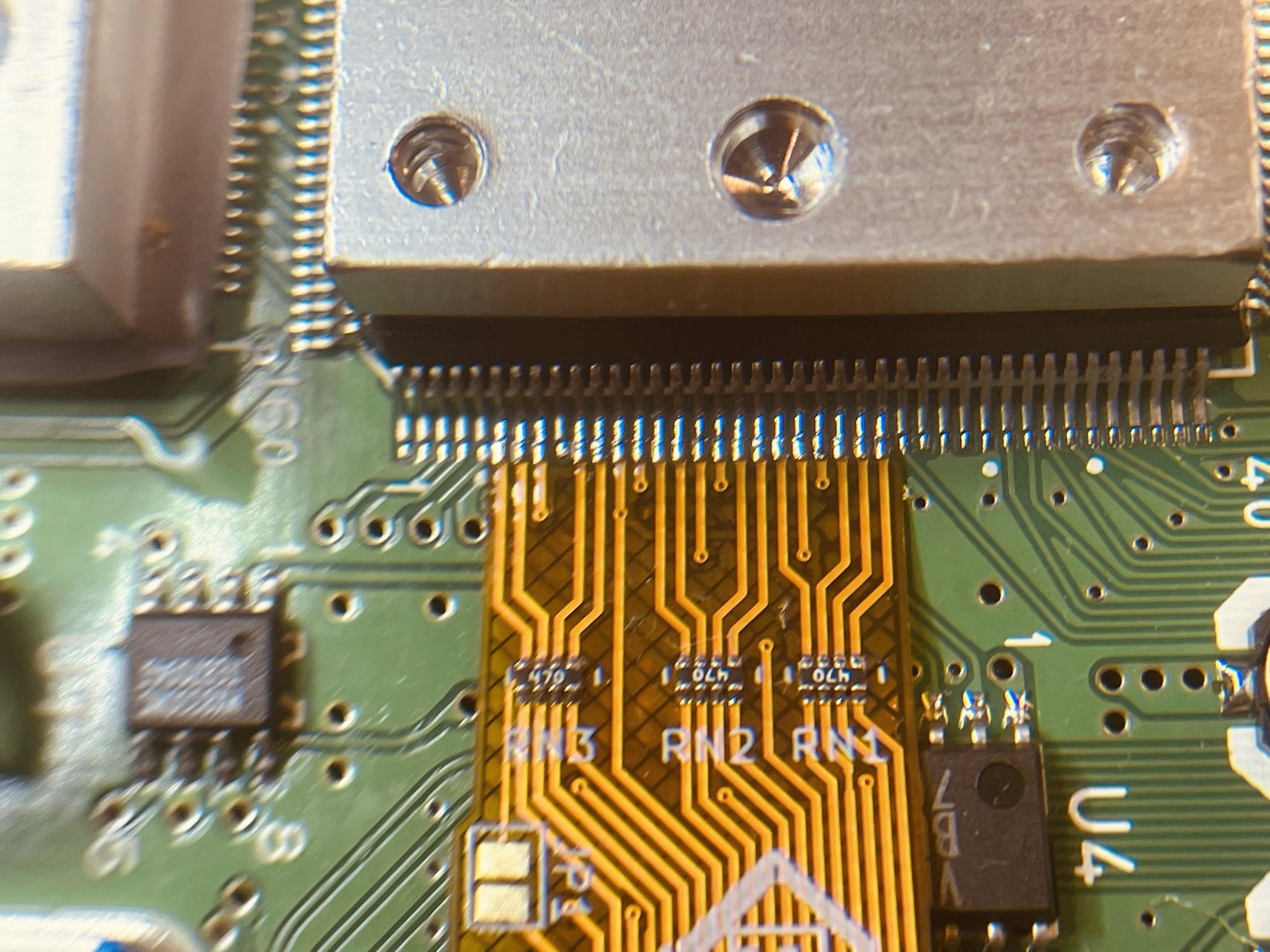
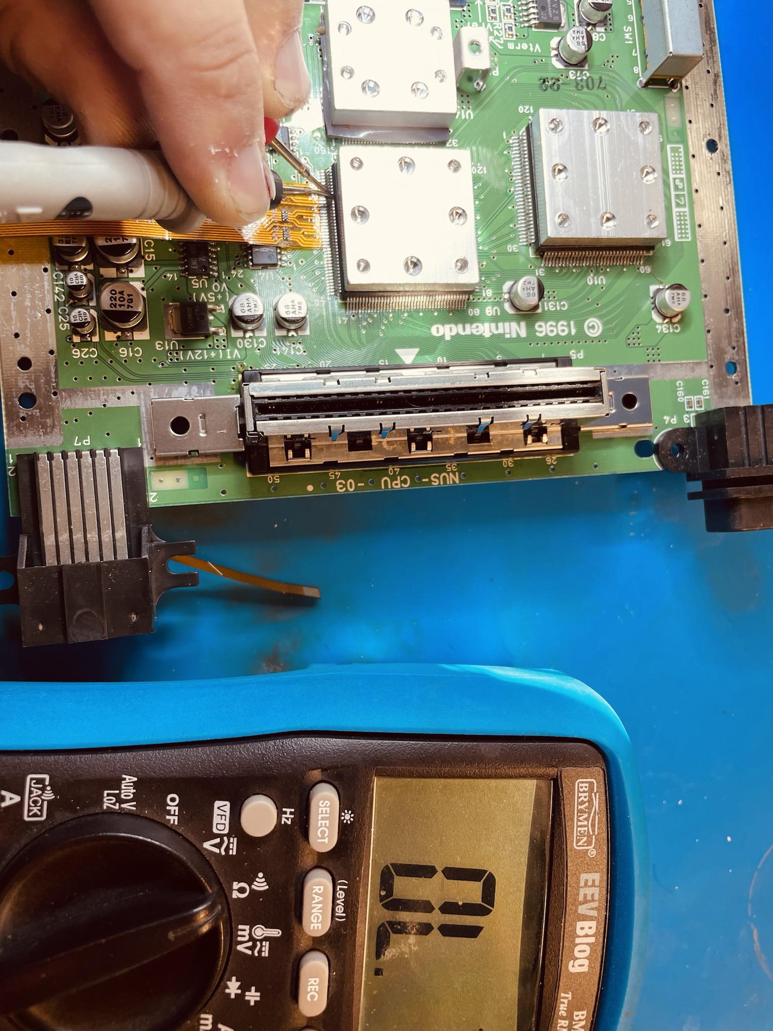
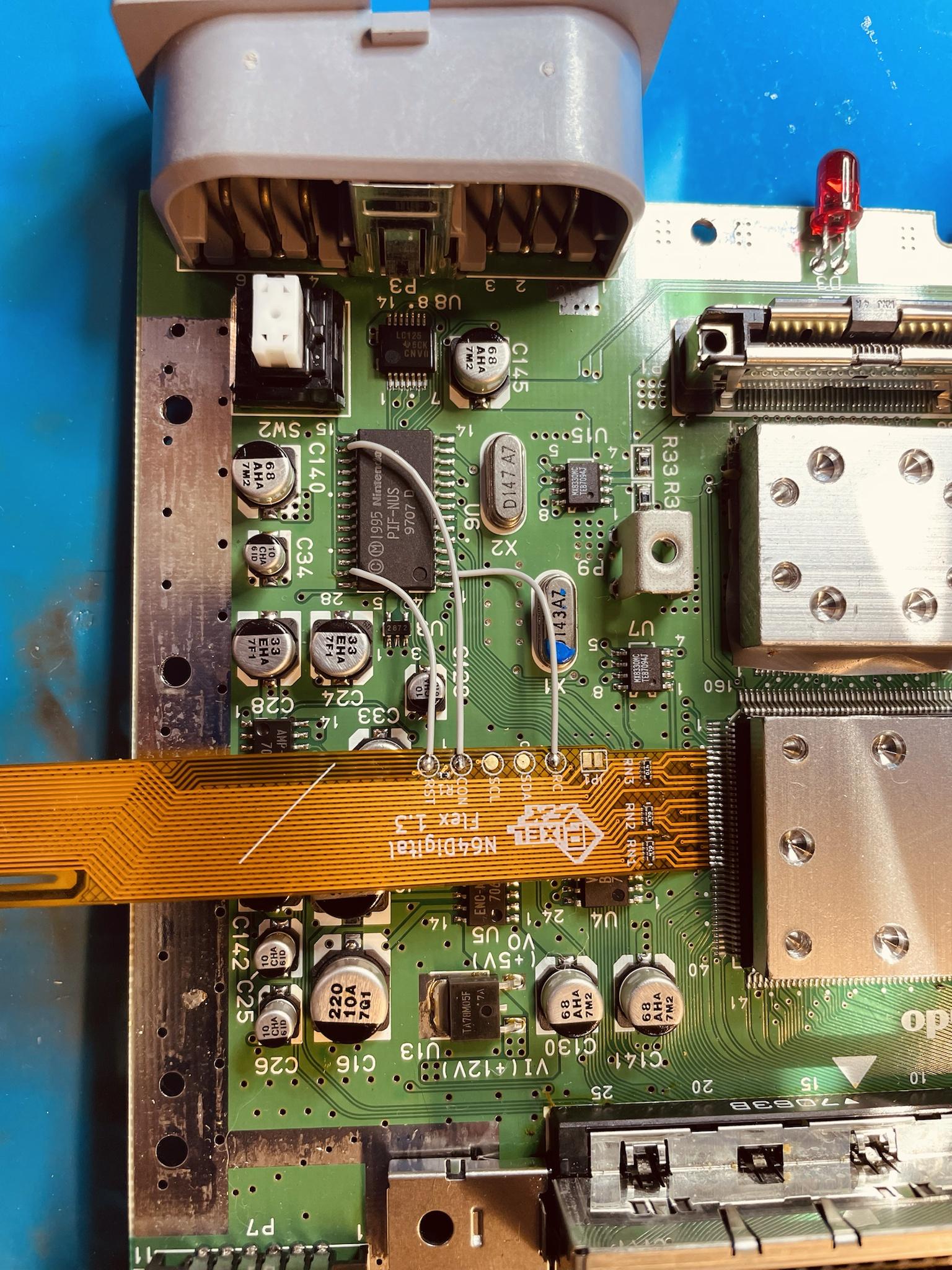
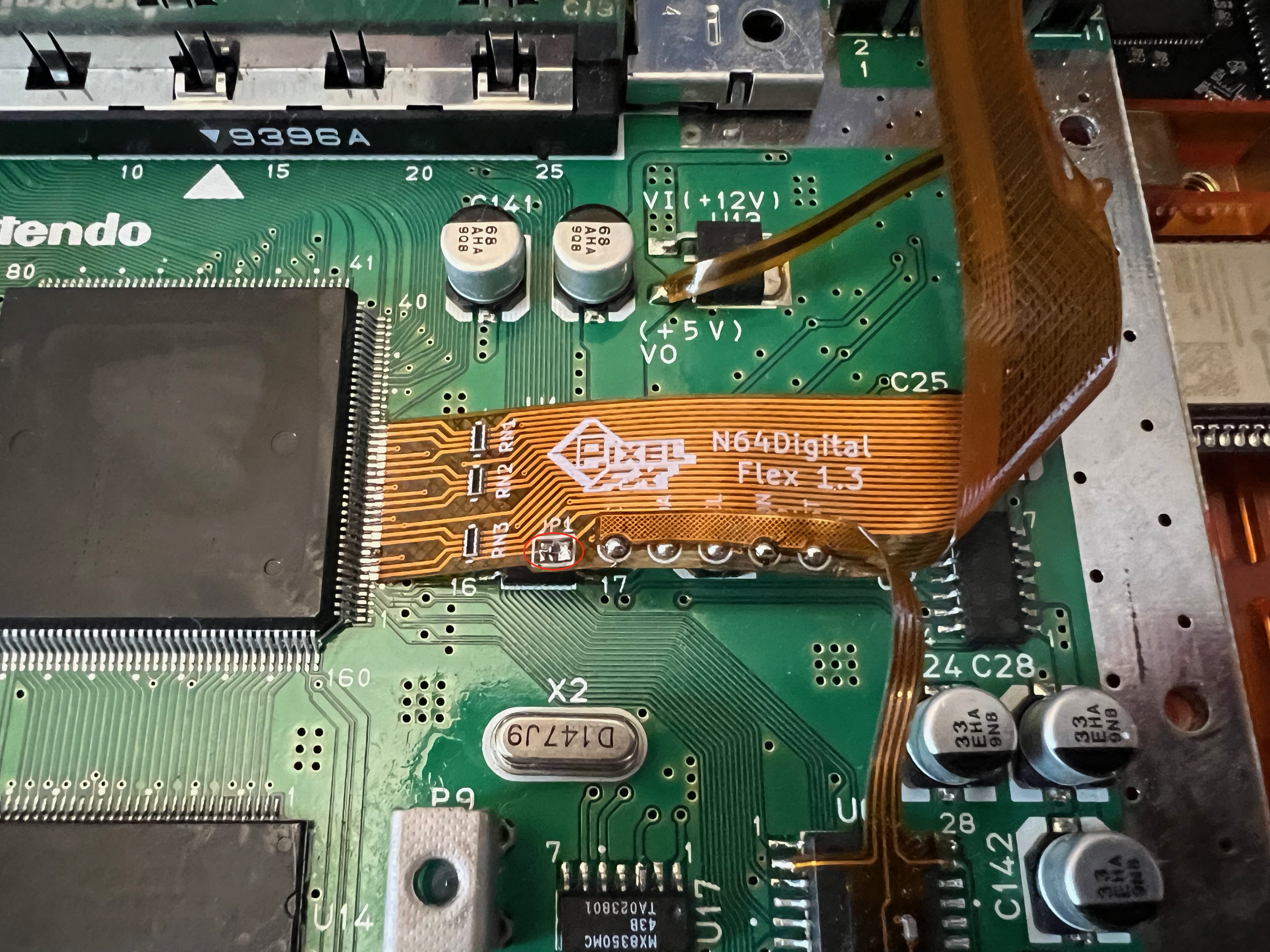
Solder the pif flex to the pif as shown below. Then solder to the main RCP flex. **Do not solder to any vias only the legs of the PIF (all mobo revisions)
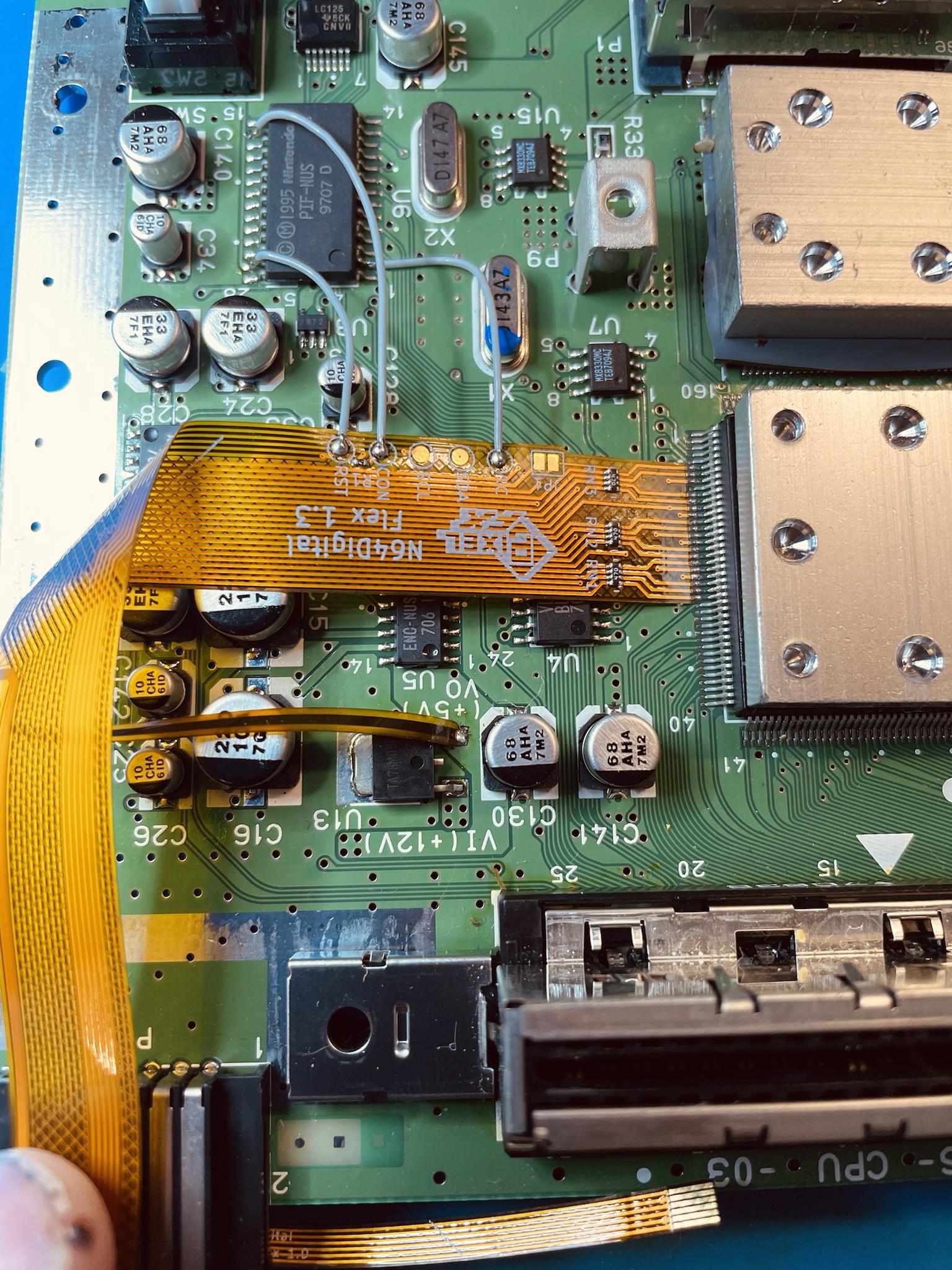
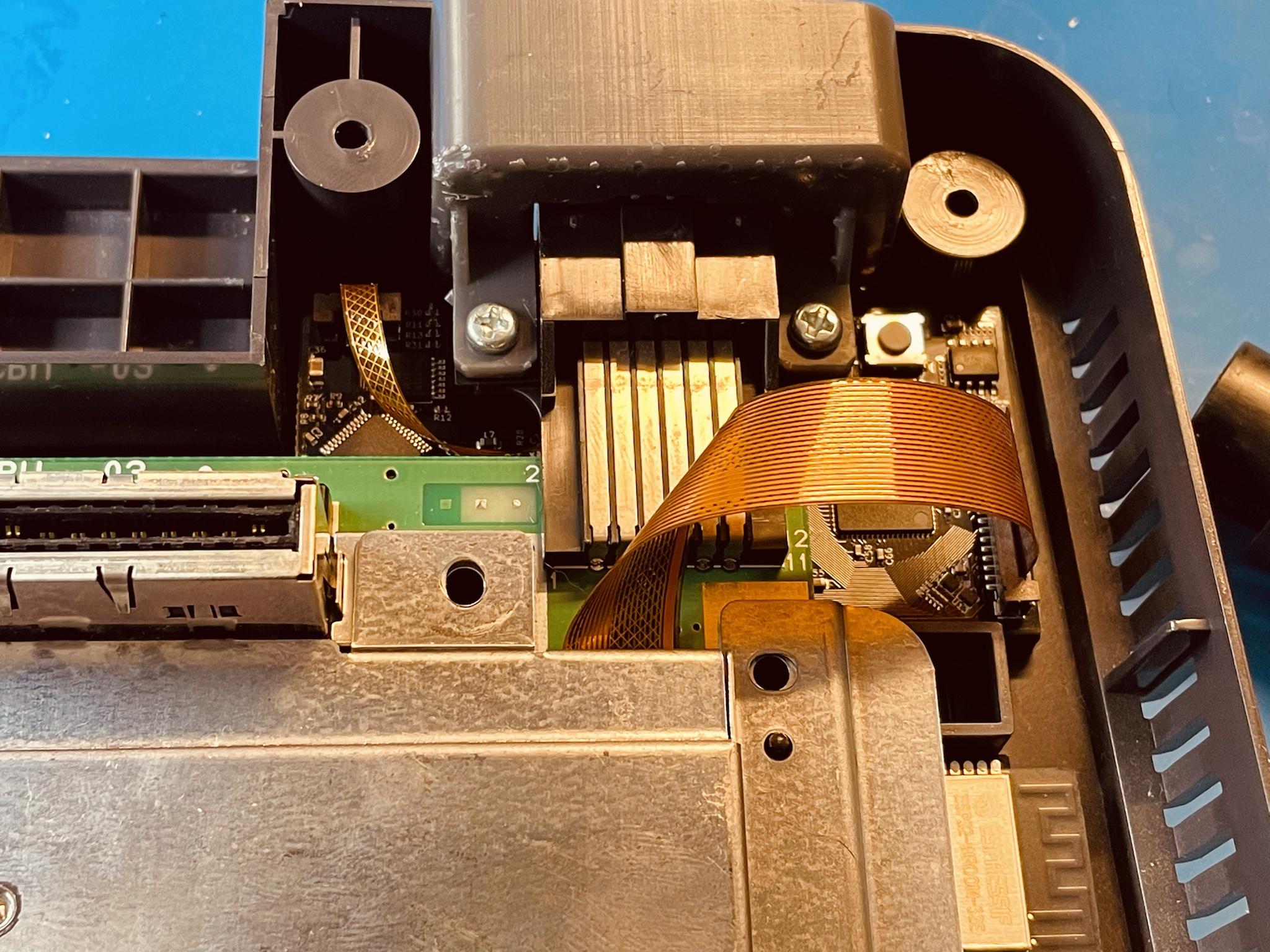
Slightly bend the RCP flex aligning it to the multiout. Refer to the image below.
Solder the flex arm to the 5V leg. Refer to the image below.
Step 5 - Testing RCP flex installation.
Click to expand/collapse
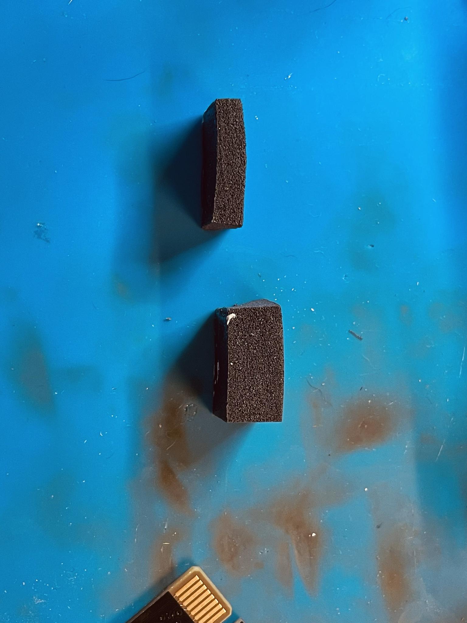
Insert the foam over the multiout pins. If using the no-cut version, cut the foam in half in terms of height. If you have HW2 use the supplied blocks. The shorter block is used for the no cut.


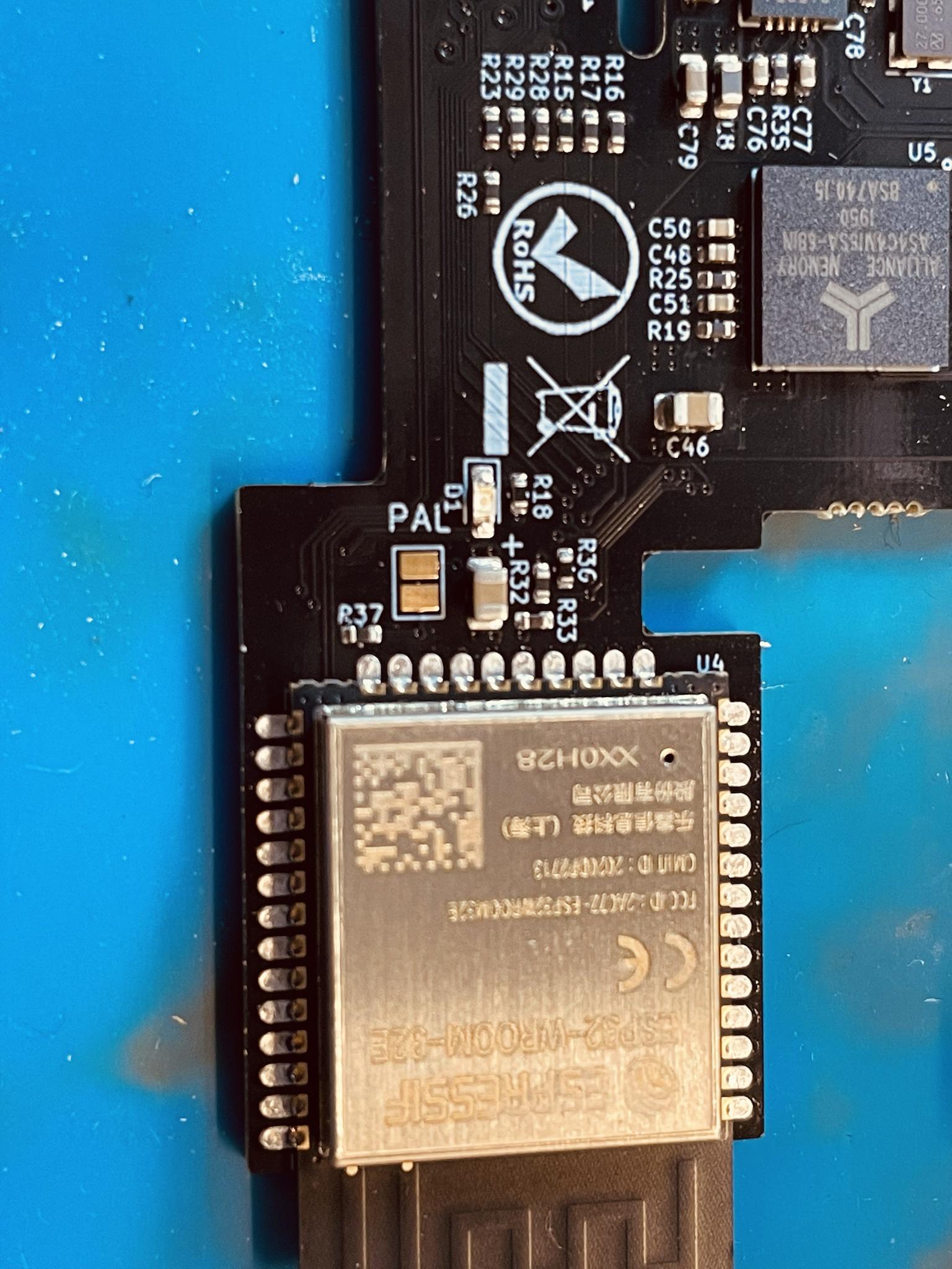
If you have a PAL console, solder the jumper found on the N64Digital PCB.
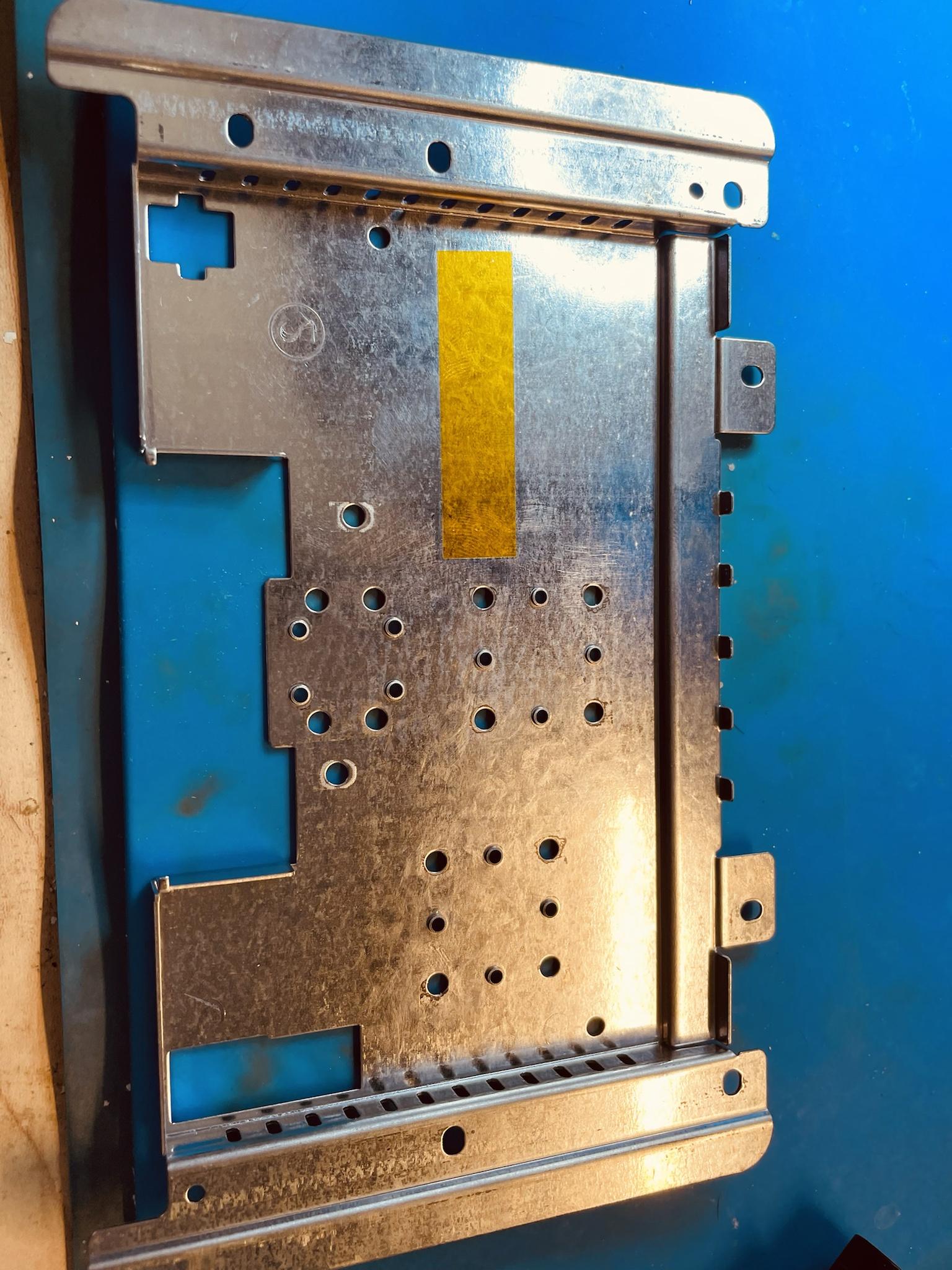
Install the bottom shield on the N64 motherboard and install the motherboard into the N64 Case. No Cut: Install the plastic spacer and N64Digital Board into the N64 case, then place the N64 Motherboard on top, do NOT use the bottom shield.
![]()
Lift the FFC connector tabs VERY GENTLY and install the RCP flex into the N64Digital board. Do not plug in the RGB flex, just keep the flex out of the way.
Important
-
Make sure the connector is free from any particals or other contamination.
It sometimes helps to use some IPA inside the connector and reinsert the flex a couple of times to dislodge them. -
Make sure the flex cable is fully inserted and perpendicular to the connector before closing the locking tab. Pay extra attention that the flex cable is properly aligned and centered when inserting. (There are guides inside the connector, which are more narrow than the space between the locking tab)
Insert game cart, mini hdmi cable, jumper pak, and controller into port 1. Double check jumper pak is correctly oriented. Verify there is no short between 3.3V and GND before moving on.
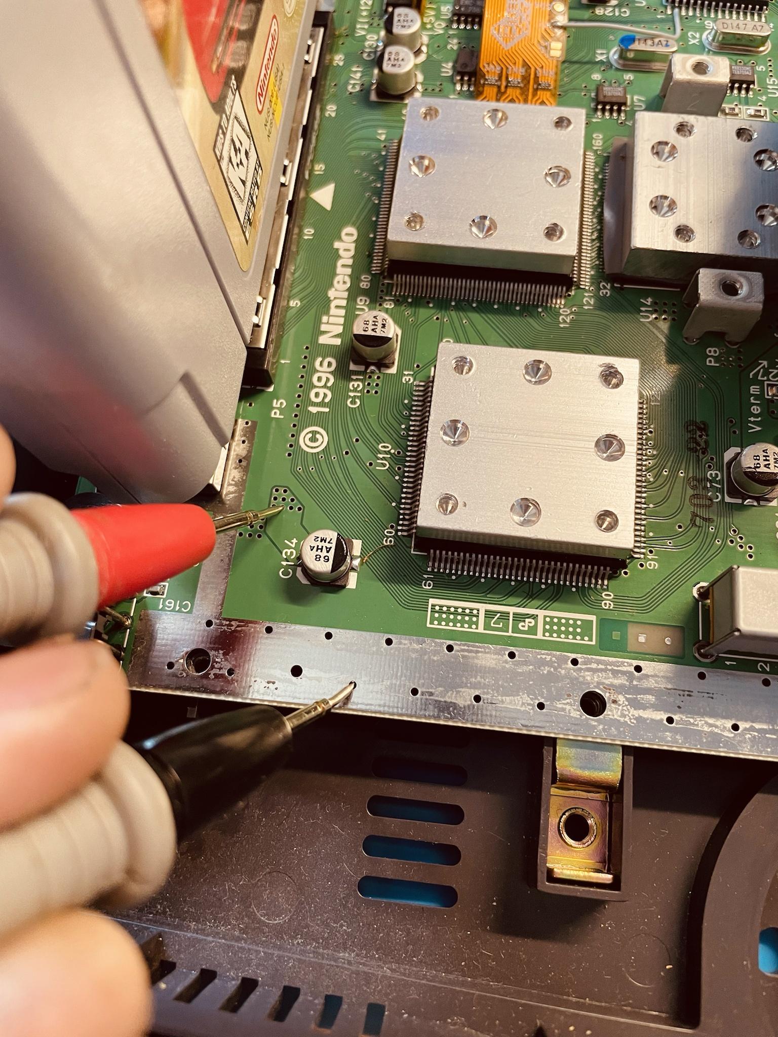
Insert N64 power supply then power on the console. Do not leave the console powered on for more than 30 seconds since the heatsink is not installed. Verify you get an image on the screen, and open up the N64 Digital OSD using: L Trigger + R Trigger + DPad Right + C Right. Confirm everything works, including sound.
After testing, remove the game cart, power supply, controller, and jumper pak.
If you do not get video and/or audio, verify the audio/video work using a composite video cable + analog audio.
- Composite doesn't work - one of two things is wrong. Bridges on the RCP flex or a poor connection with the jumper pak / game cartridge.
- Composite does work - then the issue is related to mini hdmi to hdmi adapters. Also try another TV just to rule out any issues.
DO NOT continue on until video and audio are working properly.
Step 6 - Clock Control (Optional)
Somes N64 motherboards can excibit strange behavior with the clock mod. It is recommend to not perform this mod unless you know you need it.
If you're not doing the clock mod, skip to Step 7
Click to expand/collapse
The N64Digital can recreate the original N64 clock that is sent to the RCP. With this control you can switch between PAL and NTSC frequencies when using an ED64 that has UltraCIC . Official games and older ED64 that use donor CIC will need a PIF replacement to boot out-of-region games.
Lift the pin based on your N64 motherboard revision below.
Early NTSC and PAL consoles
Late Model NTSC & PAL consoles.
Please click on your HW revision to show the final steps required to finish this step!
HW1
Close the jumper on the RCP flex cable.

HW2
Close the jumper on the N64Digital HW2 Main Board.
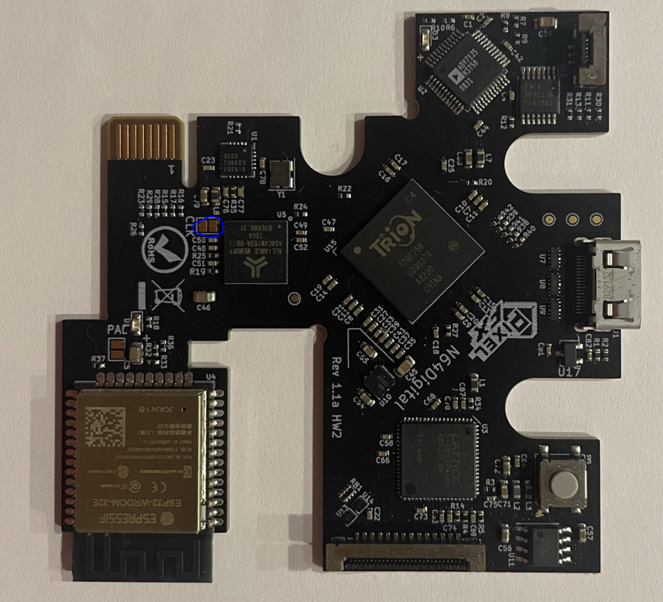
Install a 33 ohms resistor on the RCP flex cable JP1. 0805, 0603 and 0402 SMD resistors work, 0603 probably has the optimal size.
Important
After starting the console, go to OSD->System->Expert Settings and set Signal Adjust to 2.
Save with R, then power cycle your console.
Step 7 - Reassemble the console
Click to expand/collapse
Install a small piece of kapton or electrical tape on the top shield.
Install the RGB flex into the FFC connector. Be extremely gentle. It is recommended to use tweezers to help you install it.
Assemble the console in reverse order from disassembly. If you do not remember where the screws go, follow the end of the installation video https://youtu.be/LJ5PXZjXLVE
Congratulations! Enjoy the N64Digital and we appreciate your support.