Retro GEM Wii Installation Instructions
Disclaimer: This kit is for advanced installers only. Install at your own risk. We cannot be held responsible for damage to your console and/or kit. Each kit is individually tested and confirmed working before being shipped.
Before you begin:
The kit is compatible with all Wii Models. There are three different installation types depending on your Wii Motherboard. These will be reffered to as 6 Layer, 4 Layer, Wii Mini.
6 Layer Models: RVL-CPU-01, RVL-CPU-10, RVL-CPU-20,RVL-CPU-30
4 Layer Models: RVL-CPU-40,RVL-CPU-50,RVL-CPU-60,
Wii Mii: RVK-CPU-01,RVK-CPU-02
Here is a video installation of a 4 layer board. Please use it for references and techniques.
Kit includes:
- Wii Main Flex
- USB Sniffer Board
- USB Sniffer Flex
- Mini HDMI Adapter Board
- Male HDMI Adapter
- 150mm 18p FFC Cable
- FR4 Mount
- M1.6 Screw mount (2x)
- M1.6 Screw 3mm (2x)
- Wifi Antenna
- .5mm Thermal Pad
Items required
- Temperature Controlled Soldering Iron
- Leaded or Lead Free Solder
- Non-Corrosive, No Clean Flux (Amtech 559 / Kester 959T)
- 99% Isopropyl Alcohol
- Multi Meter
- Exacto Knife
- Small screw phillips screw drivers
- Side cutters
Step 0 - GEM Jumpers.
Click to expand/collapse
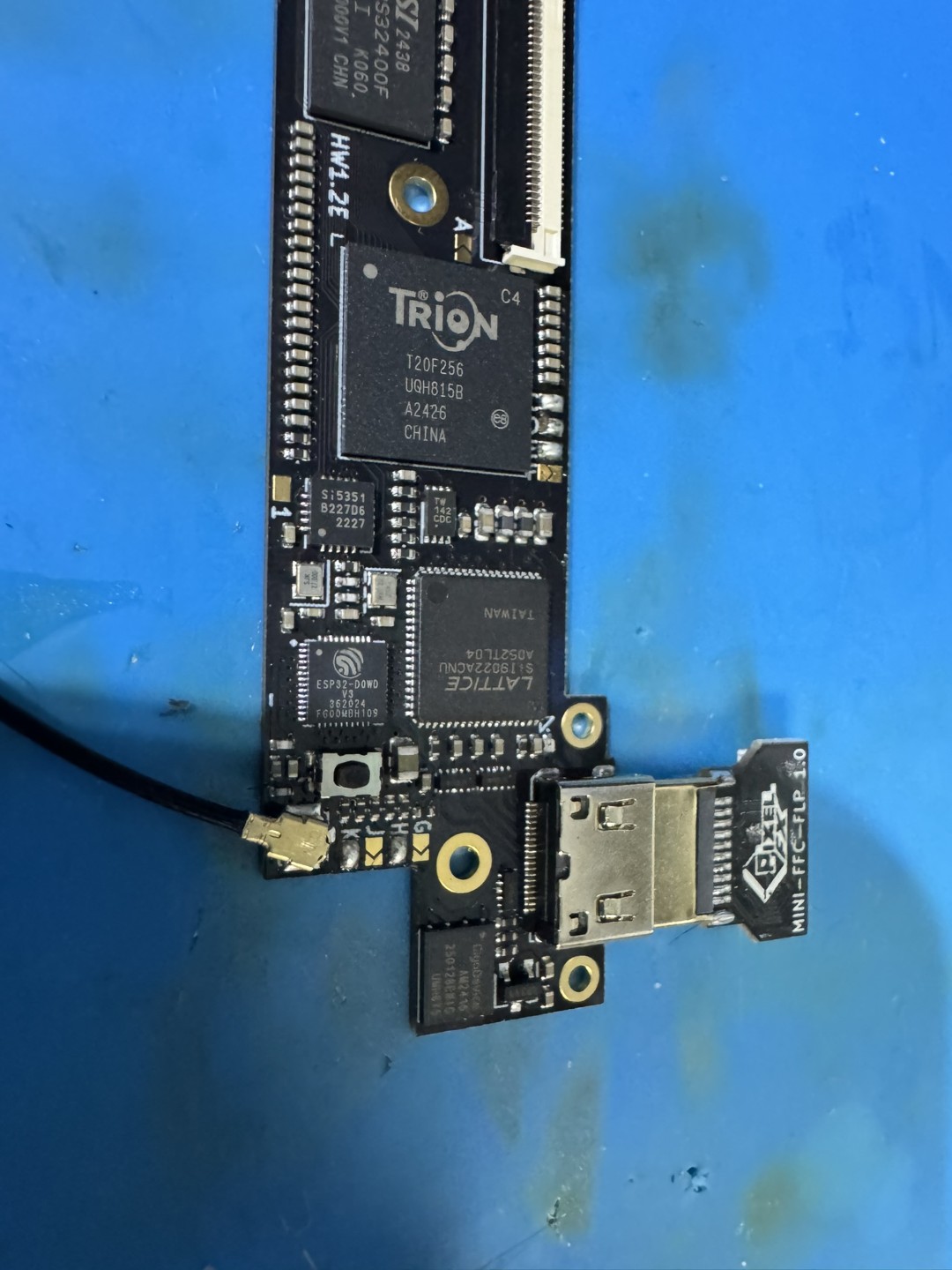
Set the Retro GEM Jumpers and attach the wifi antenna along with the mini hdmi connector. Make sure the mini hdmi is plugged in all the way sometimes it can be stuborn to insert fully.
Retro GEM jumper information:
Step 1 - Console Disassembly
Click to expand/collapse
This guide will not go over the disassembly of the Wii. Guides are available online. Please make sure the heatsink is attached to the wii when doing any power on testing. M2 screws and Nut can be use a temp solution to hold the heaksink in place without the bottom plastic. Allowing you to boot the console and still have access to the back side of the motherboard. For the Wii to display an image the Wifi/BT Dongle must be attached (Sometimes it sticks to the top metal shield during dissaembly).
Step 2 - Installing the GEM Mount & Flex
Click to expand/collapse
Please select your version below:
6 Layer
Click to expand/collapse
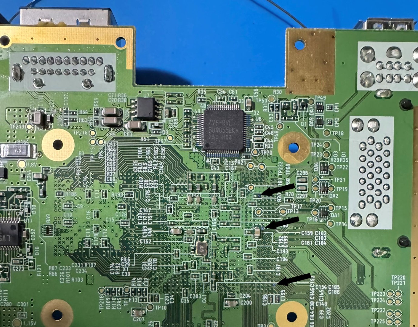
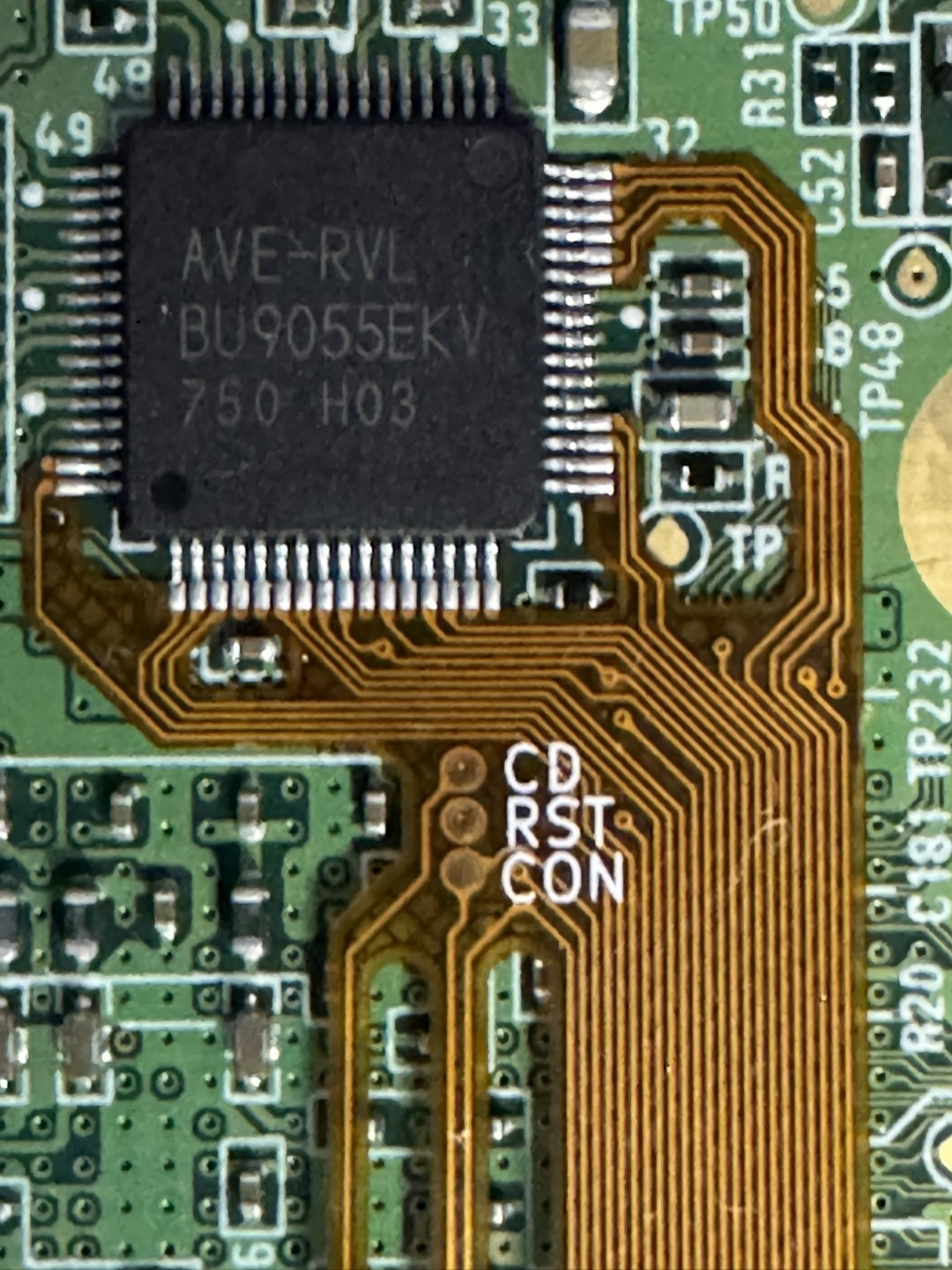
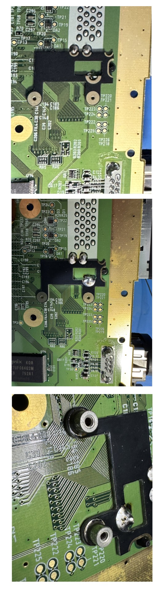
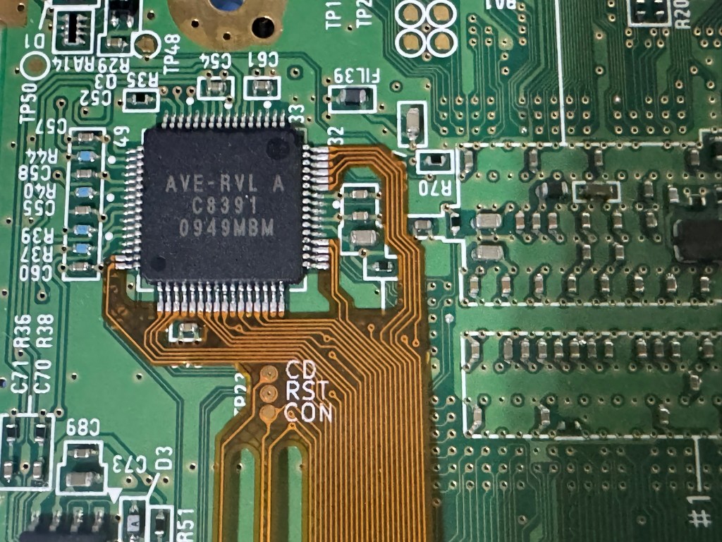
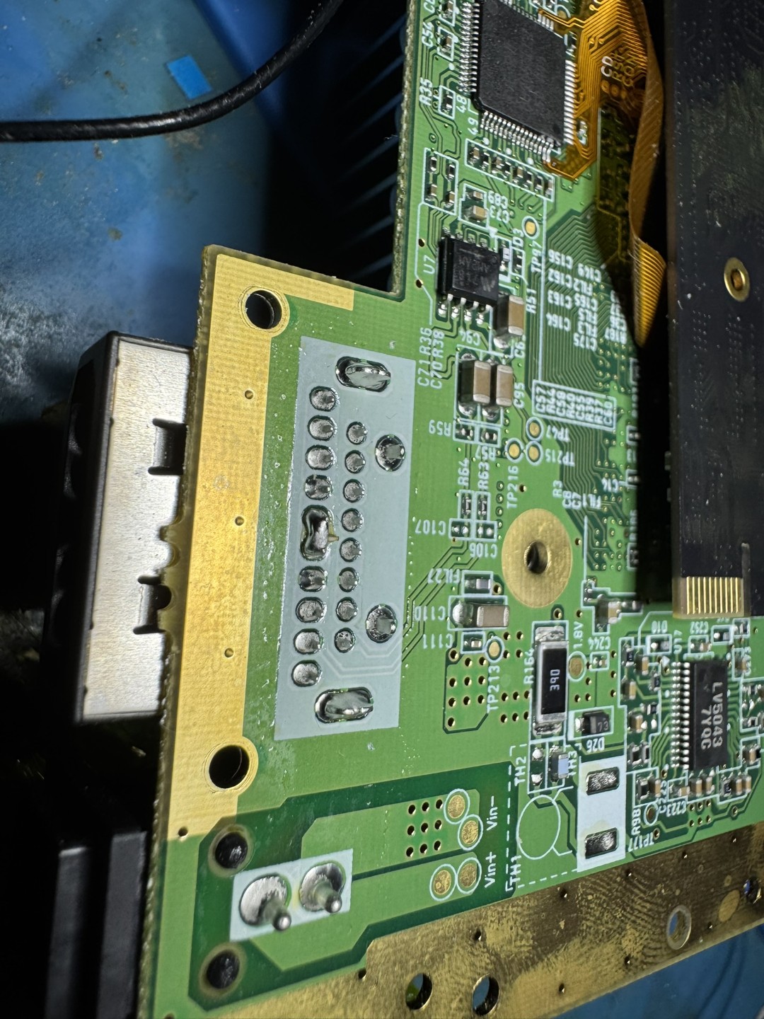
Prep all the areas highlighted in the picture for soldering. (Some vias might have soldermask that needs to be scraped off) Solder the flex to the AVE as shown in the photos.
The Wii by default uses leaded free solder. If you are using leaded solder please take the proper steps to solder wash the AVE.
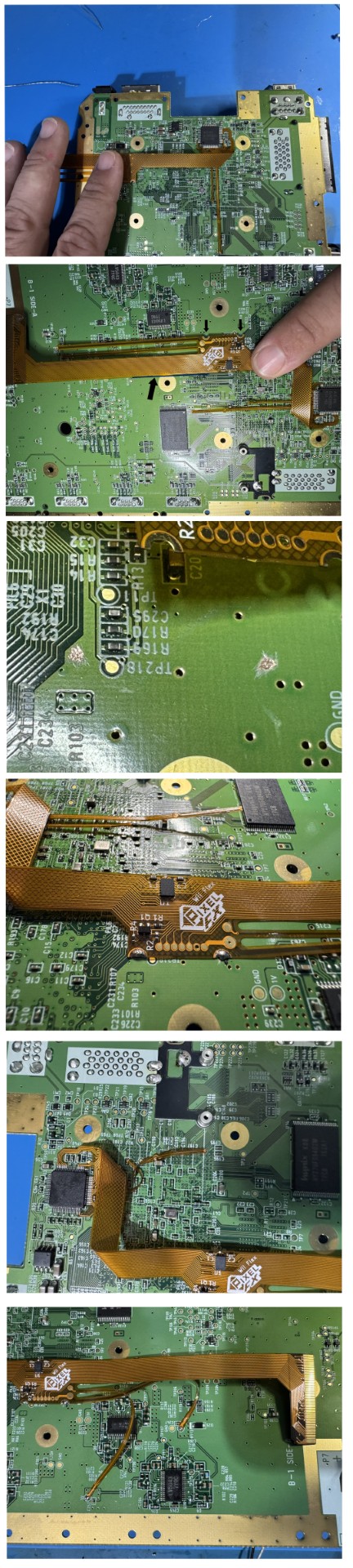
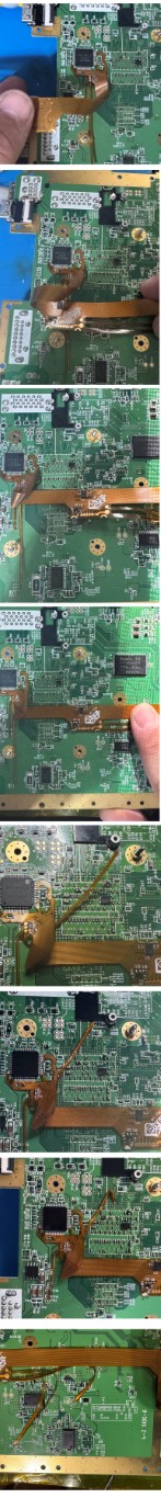
After soldering the Wii cable bend and secure as shown in the photos. Take note of the alignment of the flex cable with the Wii Motherboard screw area. Stay out of the gold circle as pointed out by the blue line. The soldermask will have to be scraped for the two ground connections to the flex. Then solder all the flex arms to their corresponding points.
Solder the GEM PCB mount and install the supplied M1.6 mounts
4 Layer
Click to expand/collapse
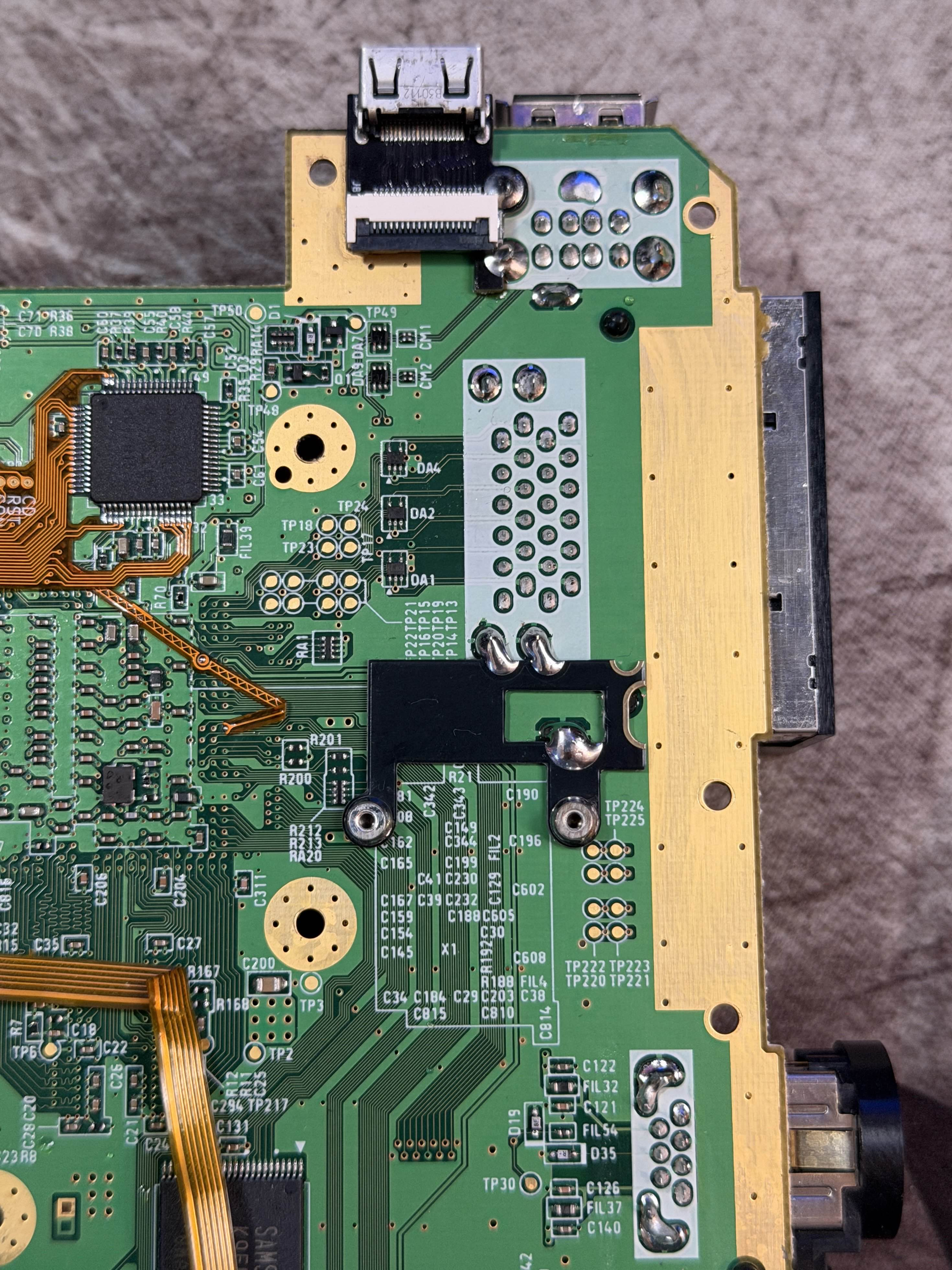
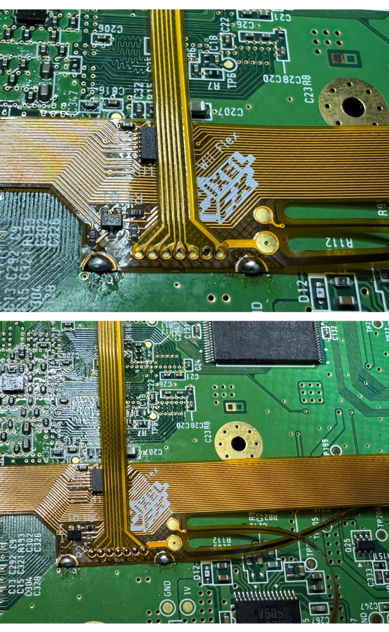
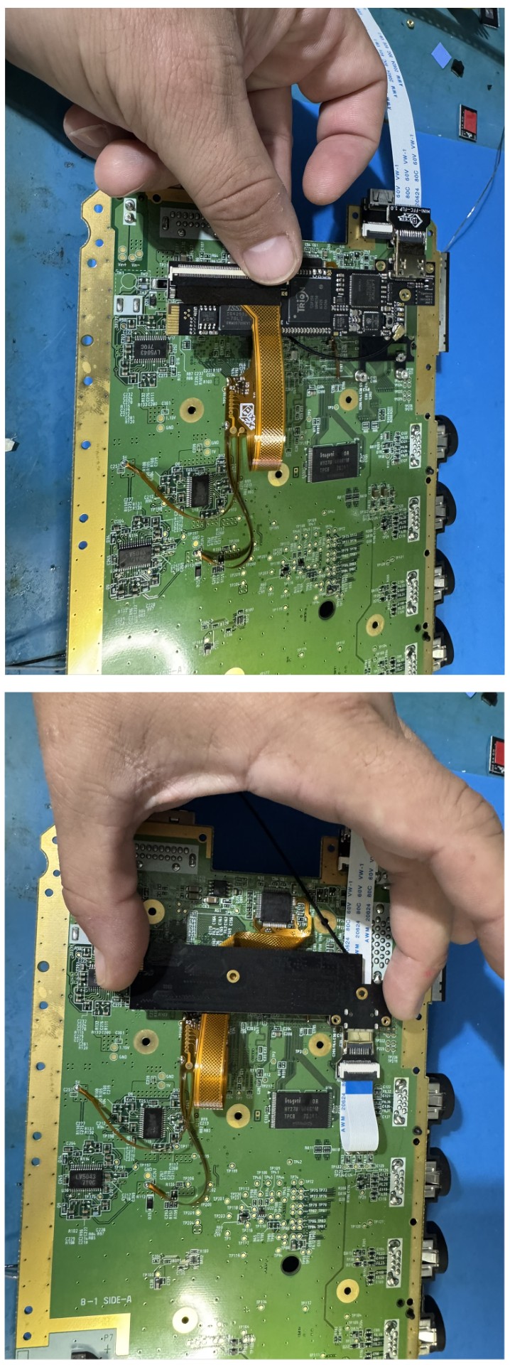
Prep all the areas highlighted in the picture for soldering. (Some vias might have soldermask that needs to be scraped off) Solder the flex to the AVE as shown in the photos.The Wii by default uses leaded free solder. If you are using leaded solder please take the proper steps to solder wash the AVE.
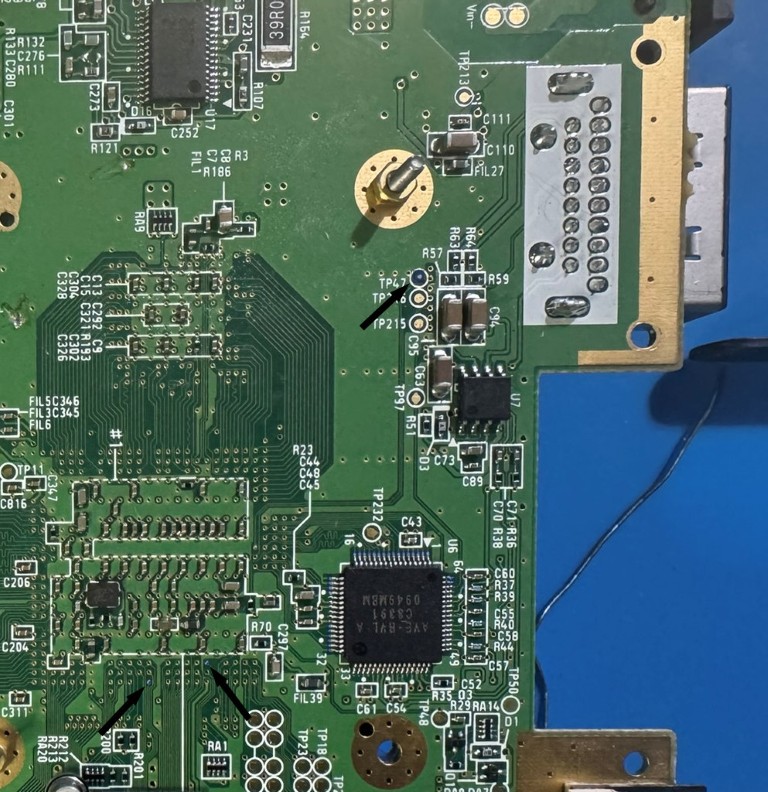
After soldering the Wii cable bend and secure as shown in the photos. Take note of the alignment of the flex cable with the Wii Motherboard screw area. Stay out of the gold mounting holes. The soldermask will have to be scraped for the two ground connections to the flex. Then solder all the flex arms to their corresponding points.
Solder the GEM PCB mount and install the supplied M1.6 mounts
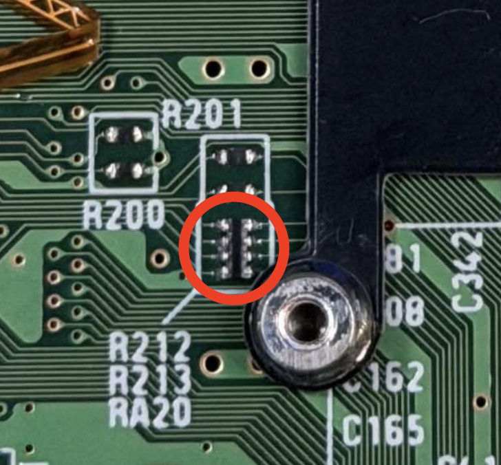
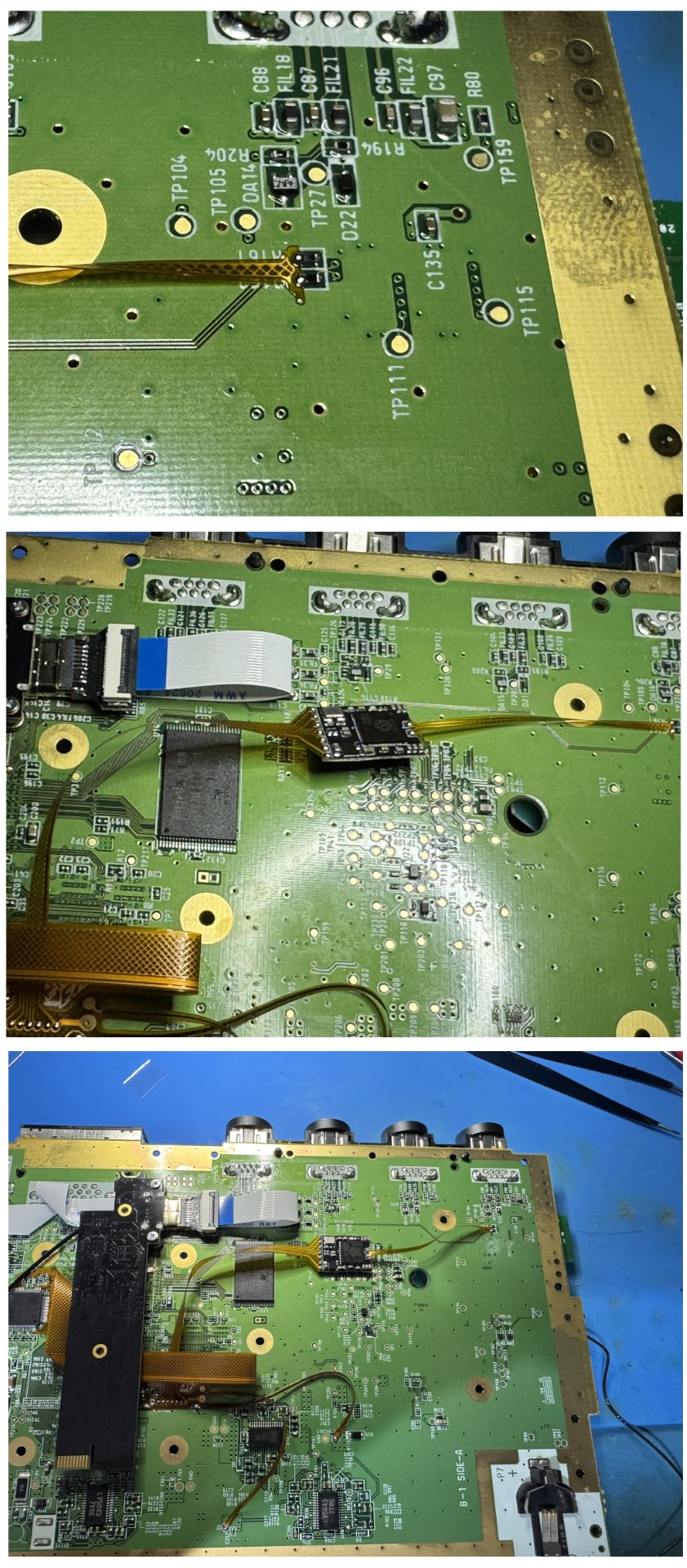
*Pay careful attention to not put the PCB MOUNT on top of any components on the Wii PCB. There is a small resistor pack can be shorted without careful attention to this area. If this resistor pack is shorted, it must be replaced. More details can be found on the discord here: https://discord.com/channels/1101136714916962364/1425610417505570959/1435257770441183376 *
Mini
Click to expand/collapse
COMING SOONStep 3 - Installing the Mini HDMI Connector and USB Sniffer
Click to expand/collapse
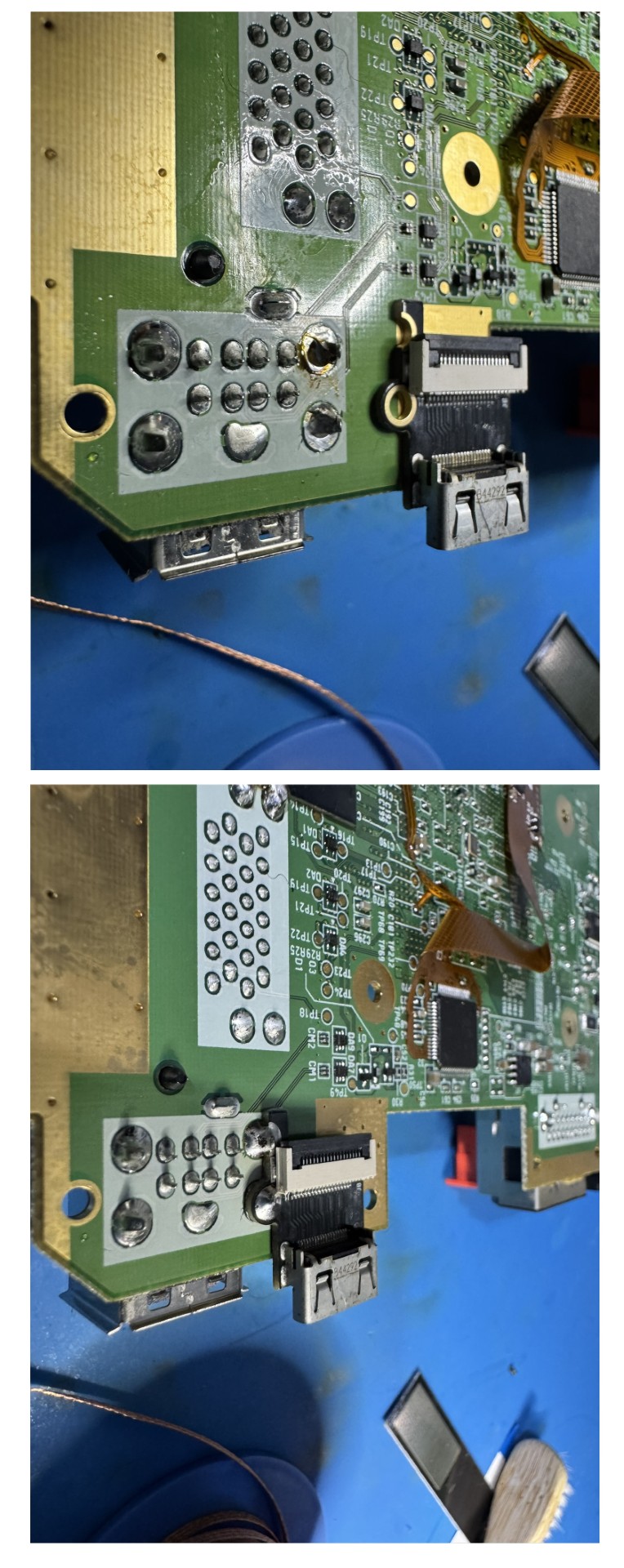
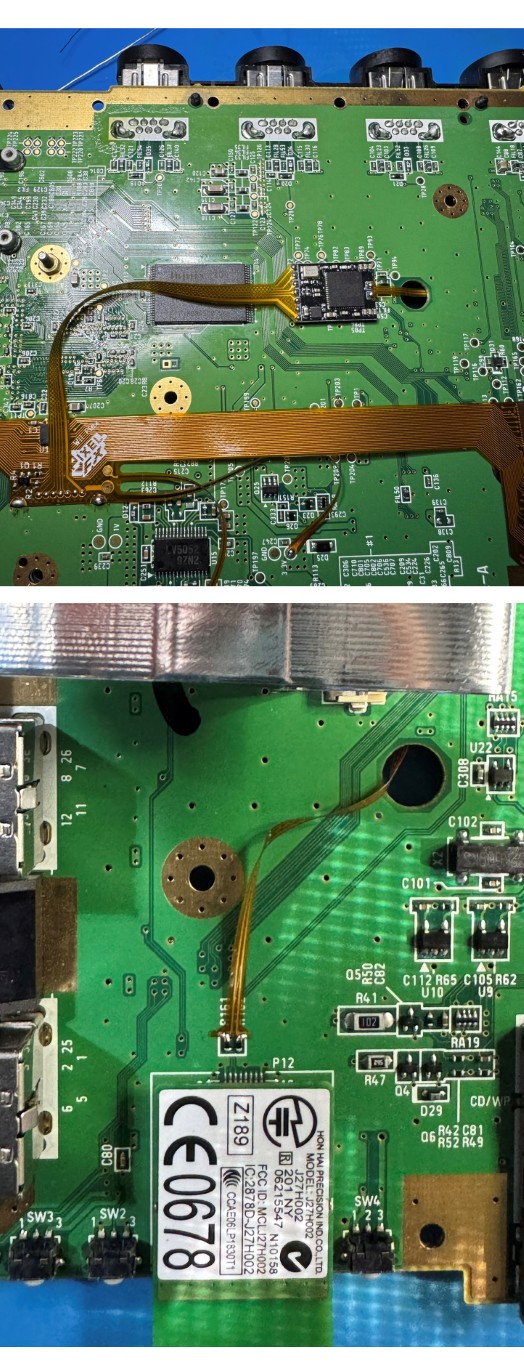
Install the Mini HDMI connector. Desolder some of the area around the points to get a better fitment. Make sure the PORT is flat and squared out with the console when attaching.
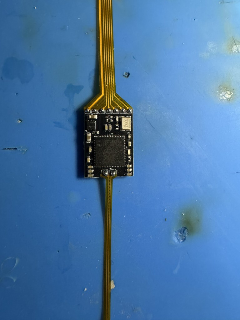
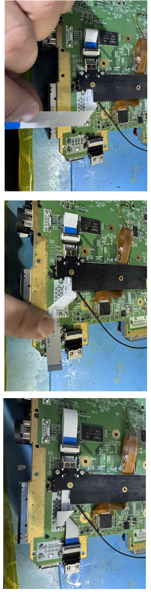
Breakdown the small flex cables to two small cables. Just grab them with your fingers and pull apart.
Attach the cables as shown to the USB Sniffer board. Pay attention to the orientation of the cables, the traces should be on the solder side.
Solder to the main flex next. Again pay attention to the orientation.
Before soldering the other side of the usb sniffer. Prep the usb sniffer by partially removing the 3M tape backer . Get your alignment and solder the flex. Take careful note of the oriention. As the hookups for the 4 layer and Wii mini will be on the top side.
Take note that flex on the 6 layer is flipped vs the 4 layer when connecting to the motherboard.
6 Layer
Click to expand/collapse
Ignore the GEM and white HDMI cable these will be installed in the next step
4 Layer
Click to expand/collapse
Mini
Click to expand/collapse
COMING SOONStep 4 - Attaching the GEM and Initial Testing
Click to expand/collapse
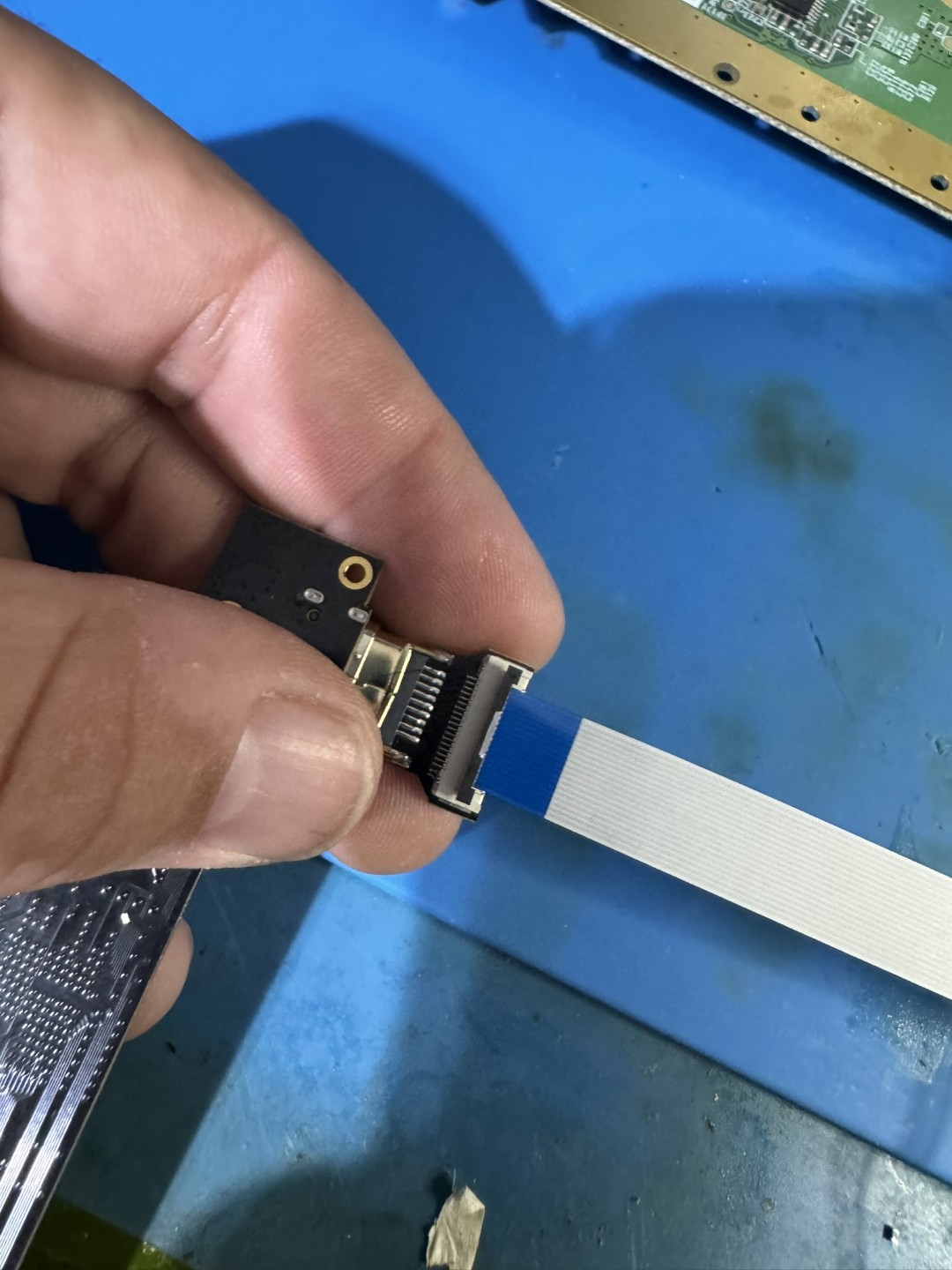
Attach the white ffc cable to the GEM's hdmi port as shown.
Now follow your specific main board instructions to finish.
4 & 6 Layer
Click to expand/collapse
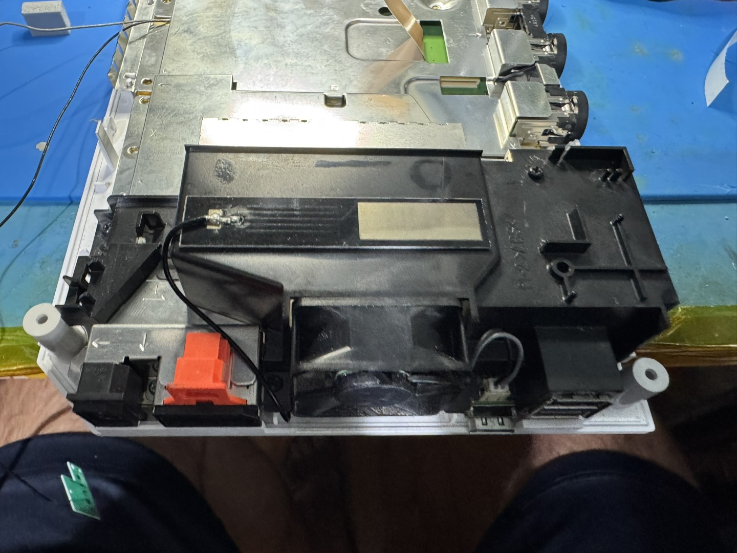
Flip the GEM over and install the main FFC connector. Attach the GEM loosly as show with the white FFC cable going underneight. Make sure its not snagged by any components.
The white ffc cable needs to flipped 180 to make the correct mating orentation. Follow the steps closely to bend the cable and then plug into the mini HDMI cable. Do not pinch the FFC cable too tight, just light pressure is all that is needed. Tighten down the gem screws after the hdmi cable is routed.
Bridge the pins shown to enable 480p support, FYI this will also disable composite support.
Wii Mini
Click to expand/collapse
COMING SOONNow is a good time to check the installation. But remember to keep the heatsink attached when testing.
Open up the OSD
-WiiMote A + B + Home -GC Controller L Trigger + R Trigger + DPad Right + X
After confirming the GEM is working its type to finish up the install.
Step 5 - Finishing Up
Click to expand/collapse
If using the bottom metal shield you must use the supplied thermal pad. The bottom metal shield can be omitted and thus the thermal pad is required in this instance.
4 & 6 Layer
Click to expand/collapse
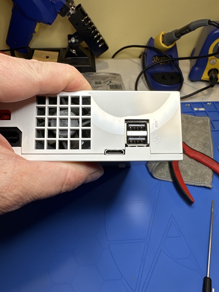
The metal shield needs to be trimmed (Side cutters, fatigue bending etc) to clear the HDMI port as shown. Once trimmed, install the thermal pad on the back of the gem. Then use some side cutters to trim any plastic on the bottom side. THis area is where the HDMI port goes. Resassemble the bottom case and motherboard and route the Wifi antenna as shown. *Make sure its not pinched when securing the heatsink.*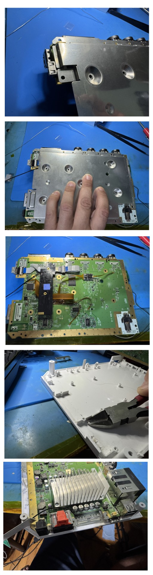
Now is another good time to check the install. The fan can be install to do longer testing. There is nothing more annoying than putting the console back together only to have to completly dissaemble again.
Part of the top case must be trimmed for the Mini HDMI to clear. Just small cut and file is needed.
After testing, put the console backtogether. Install the wifi antenna as shown
Wii Mini
Click to expand/collapse
COMING SOONIf you made it congratulations! This is no easy feat and you should be proud.