Retro GEM PS2 Slim Installation Instructions
Disclaimer: This kit is for advanced installers only. Install at your own risk. We cannot be held responsible for damage to your console and/or kit. Each kit is individually tested and confirmed working before being shipped.
Before you begin:
Please review the installation video. Always reference these install docs and use the video as an aid for techniques on how to preform the required steps.
https://youtu.be/9JkMKWqYDYc
Kit includes:
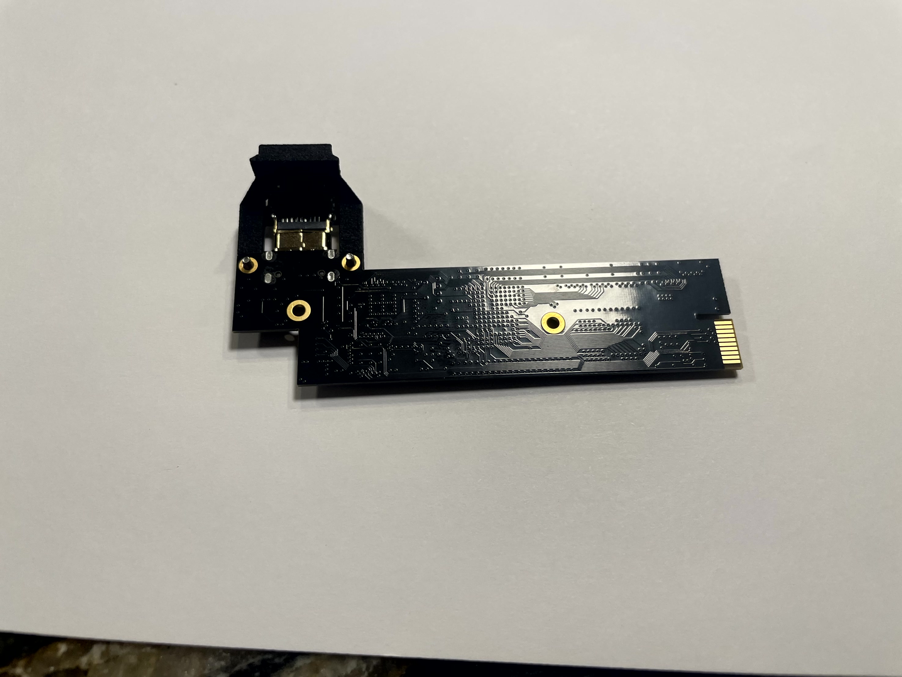
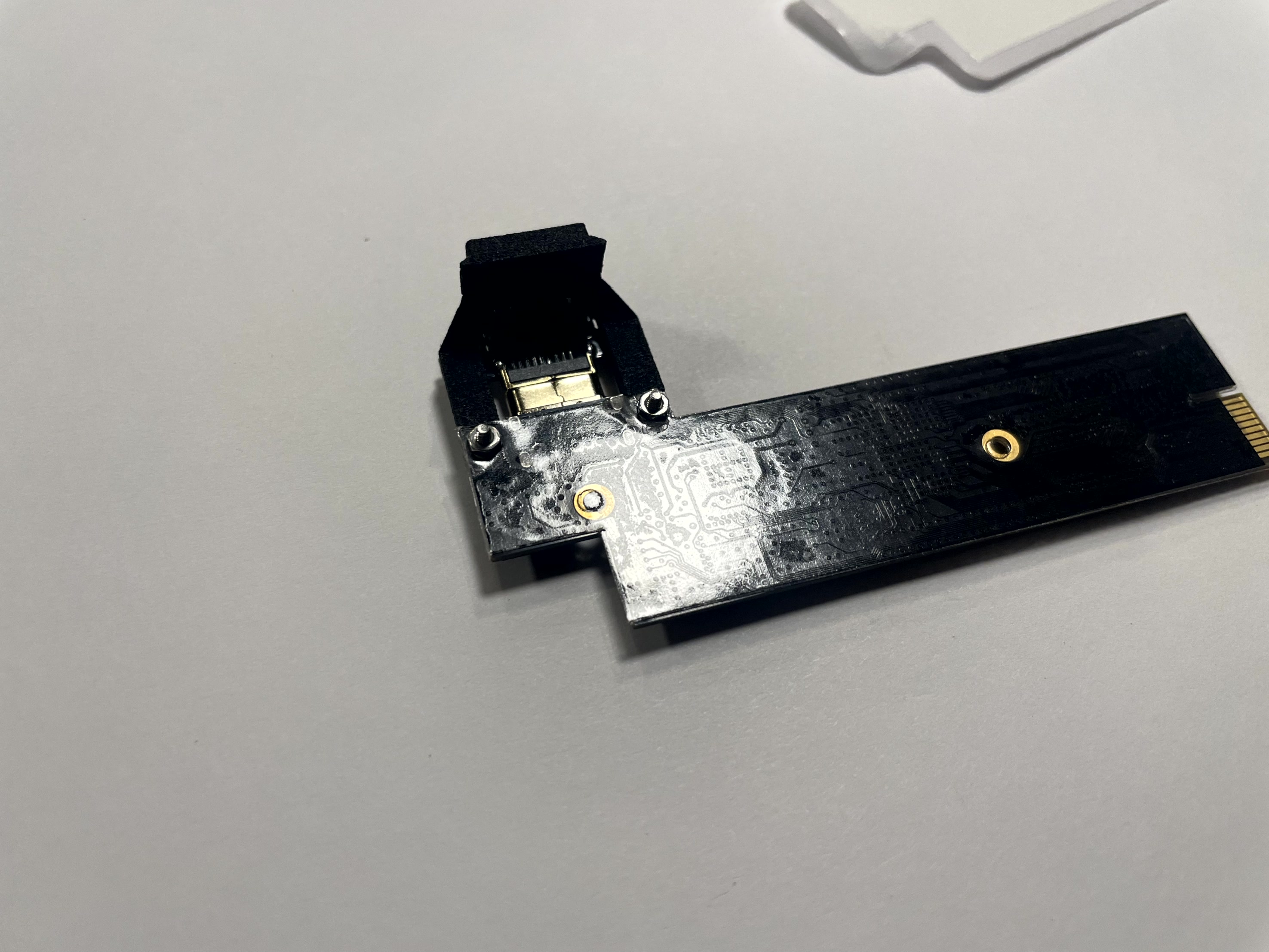
- PS2 Slim Main Flex
- PS2 Slim Controller + Audio Flex
- PS2 Slim Intermediate Flex
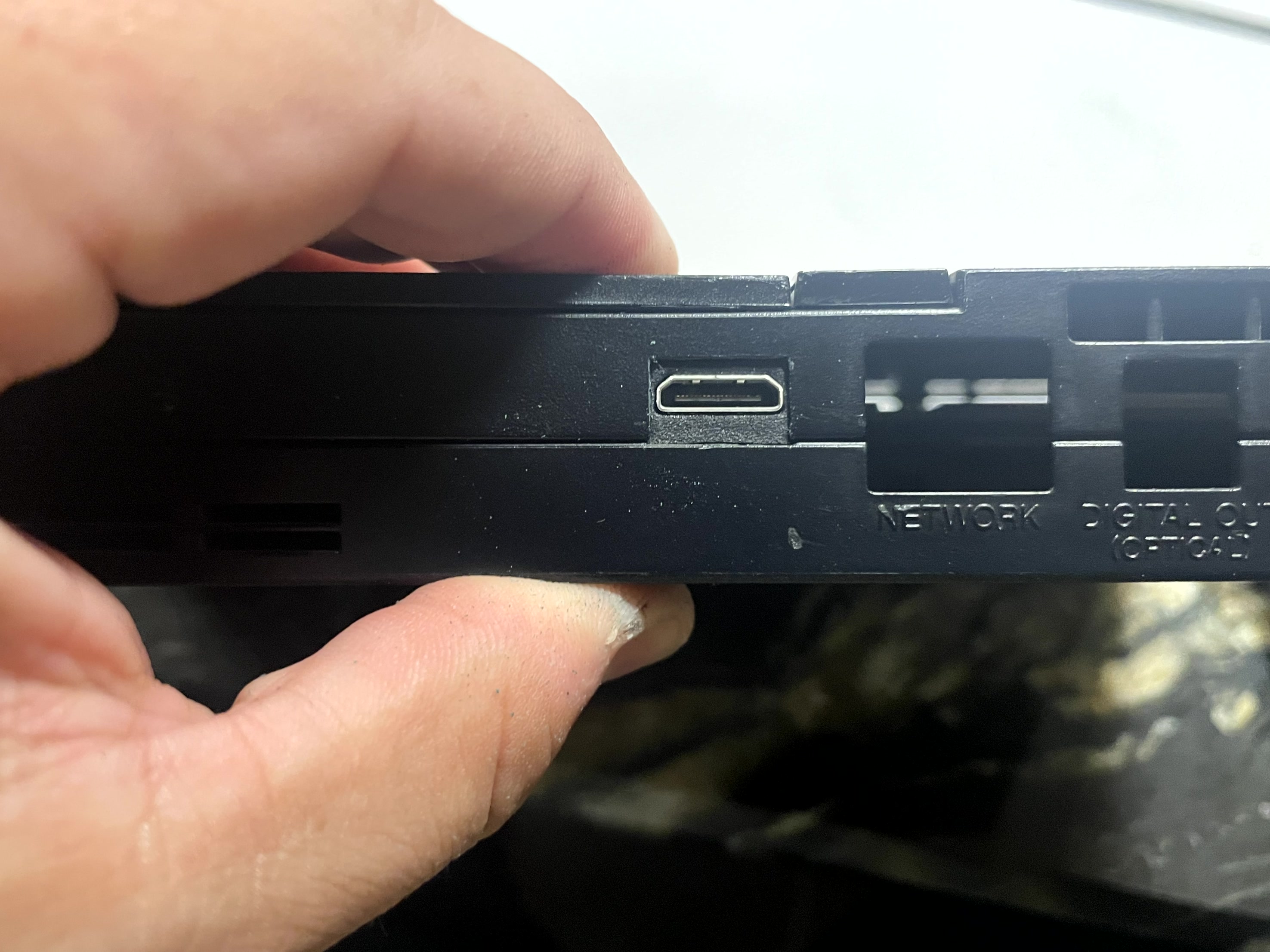
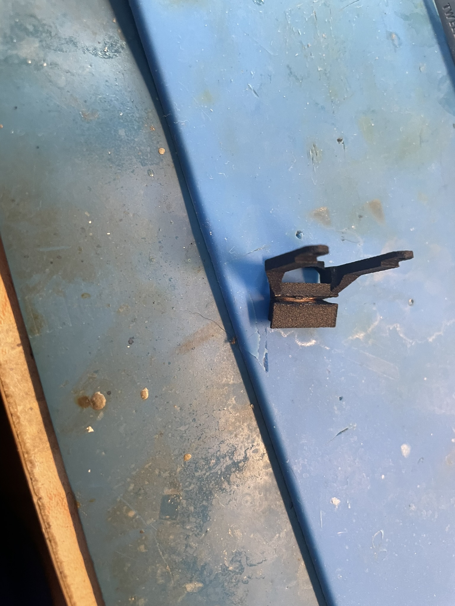
- PS2 HDMI Mount
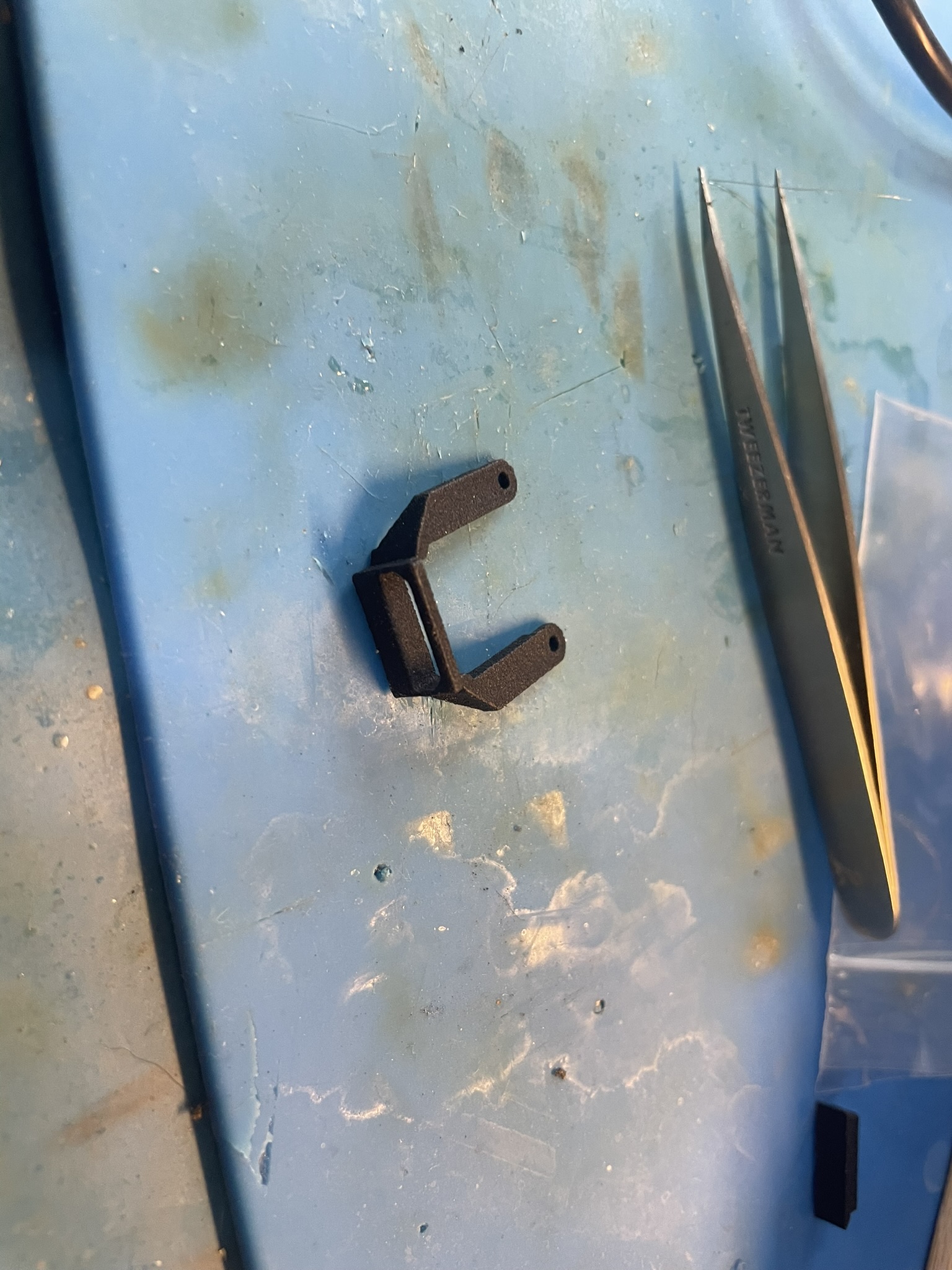
- Plastic Mount
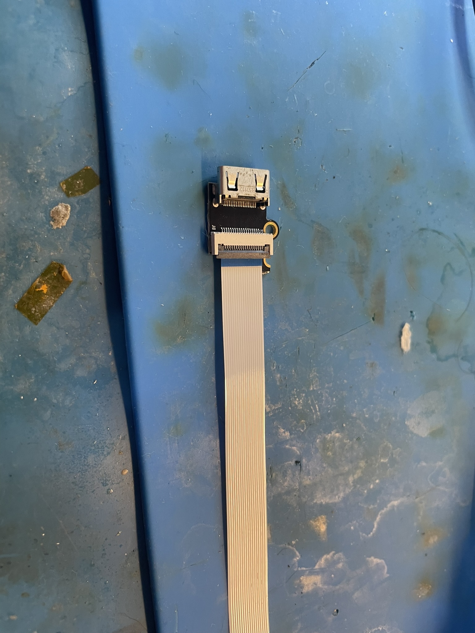
- Mini Flip HDMI Adapter
- M3 6m Screw (1x)
- M2 Nut (2x)
- M2 4mm Screw (2x)
- M1.6 Screw (2x)
- M1.6 Nut (2x)
Items required
- Temperature Controlled Soldering Iron
- Leaded Solder
- Non Corrosive, No Clean Flux (Amtech 559 / Kester 959T)
- 99% Isopropyl Alcohol
- Multi Meter
- Solder Braid / Desoldering Tools
- Small Phillips screw drivers
- Kapton Tape
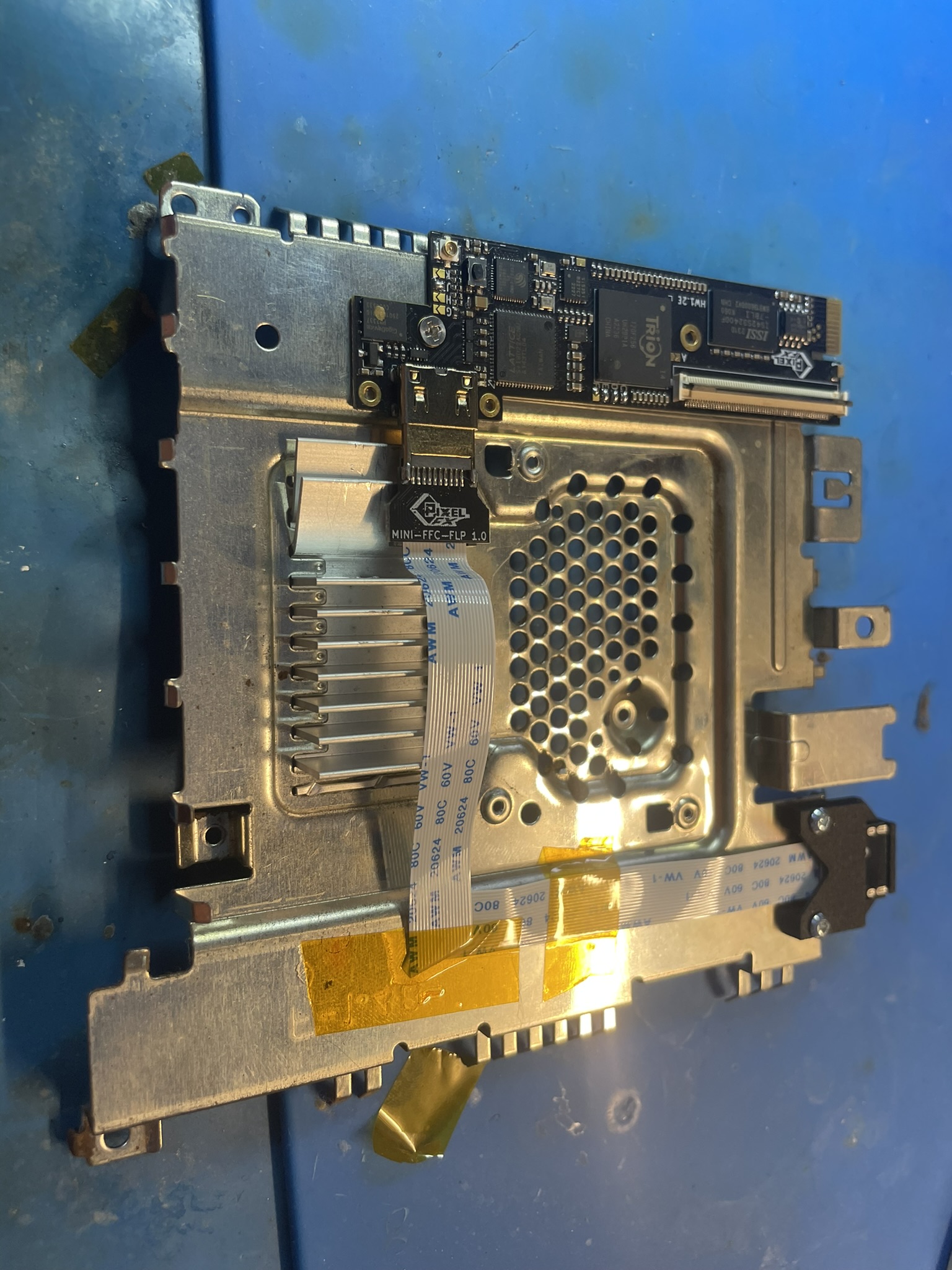
Step 0 - Understanding the GEM Kit and Setting the GEM Jumpers.
Use the online config tool to setup the jumpers for your retro gem. Just bridge the jumpers shown in the tool.
https://docs.pixelfx.co/fxdigital-config.html?c=ps2
This guide will not go over the tear down or small nuances of the installation. Please watch the installation videos for this information. (Do not TEAR the DVD drive FFC cable, these are fragile)
The typical install procedure is:
- Test the console (Don't install your kit into a non working console)
- Teardown the console
- Mounting the GEM board
- Controller/Audio Flex installation
- Main Flex installation
- Testing
- Reassembly
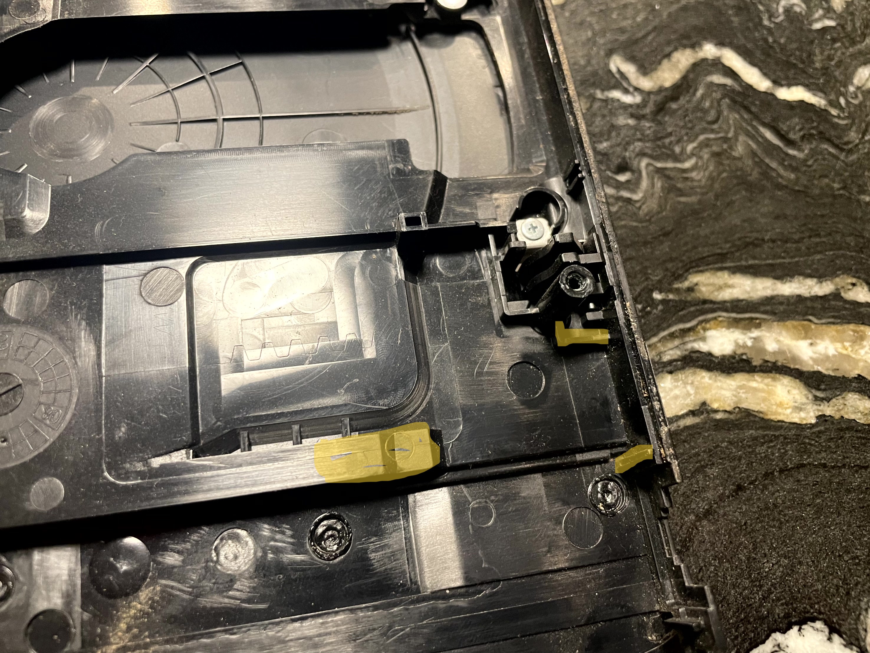
Step 1a - Mounting the GEM board (Pre 79K)
Click to expand/collapse
With your PS2 slim tore down the first step is to mount the gem board to the top shield, PS2 slims with a 56k modem are much eaiser to install.
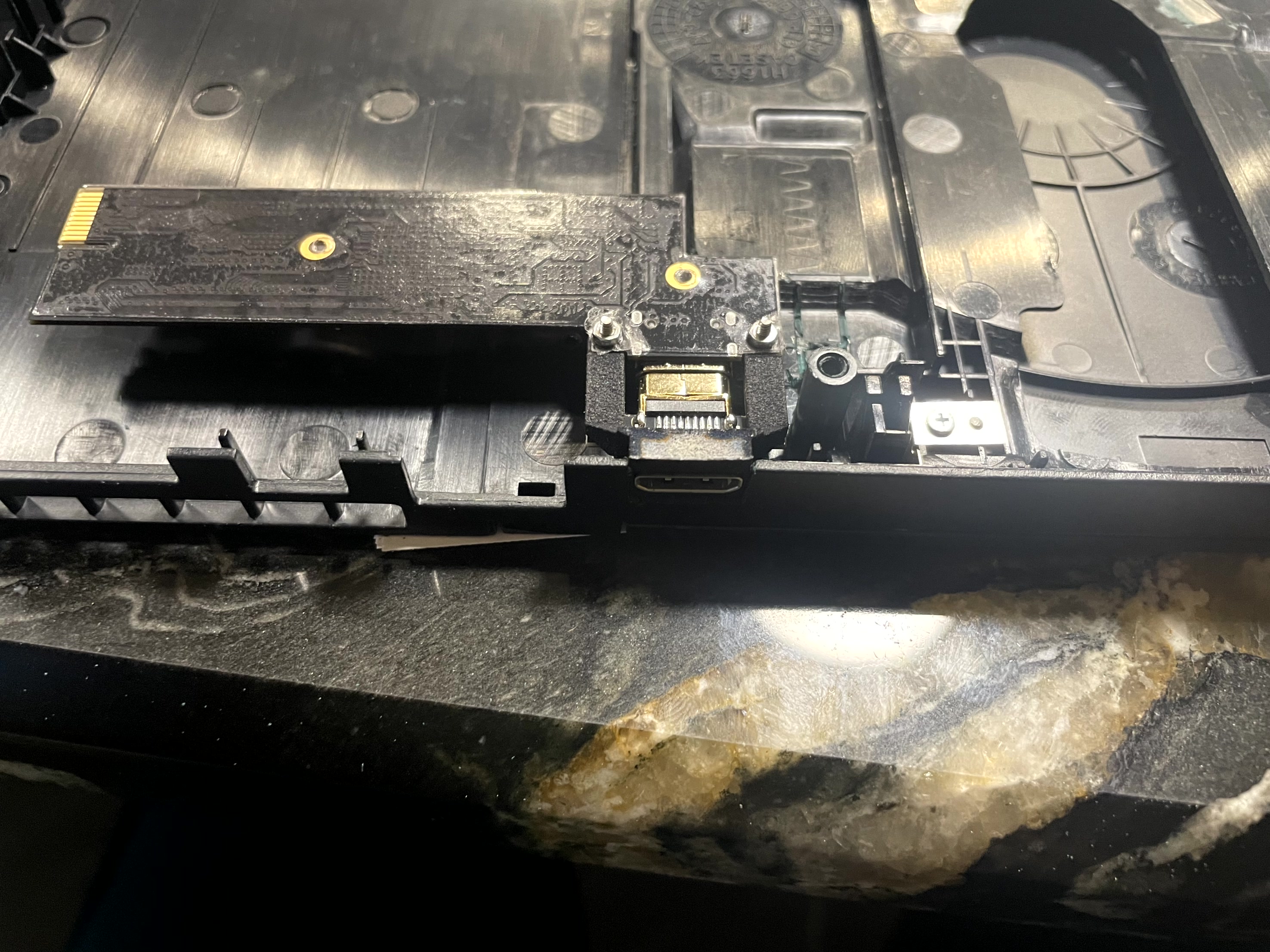
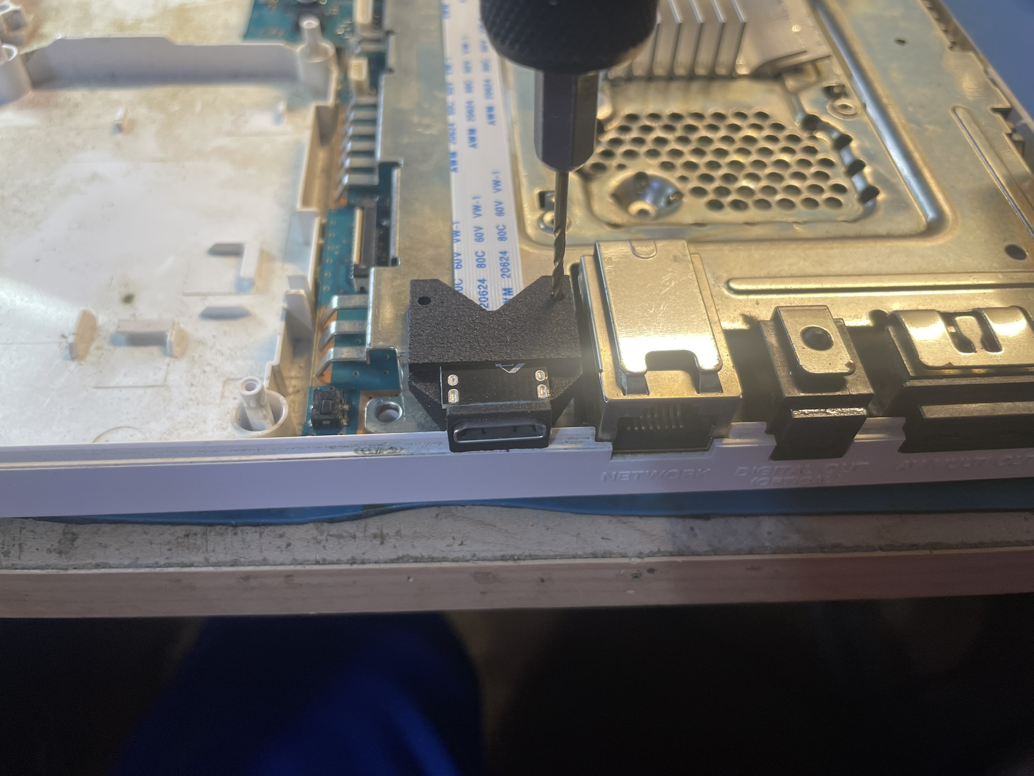
Attached the HDMI extention/cover to the mount as shown. Use the M1.6 screws.
- Do not install the nuts yet.
- Use the M1.6 screws as a guide to install the clear backing.
- After installing the backing, install the nuts do not over tighten.
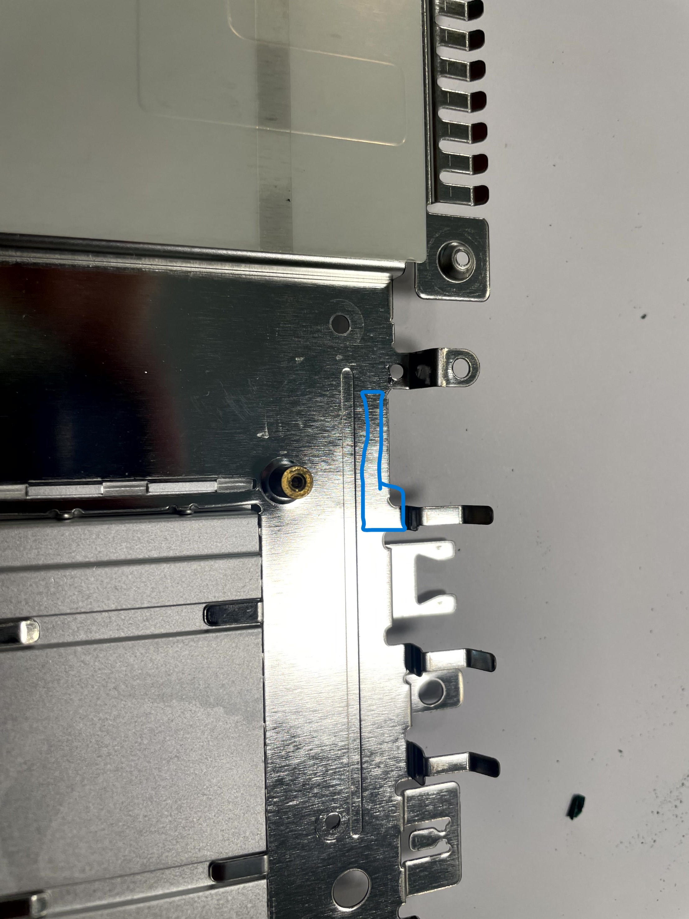
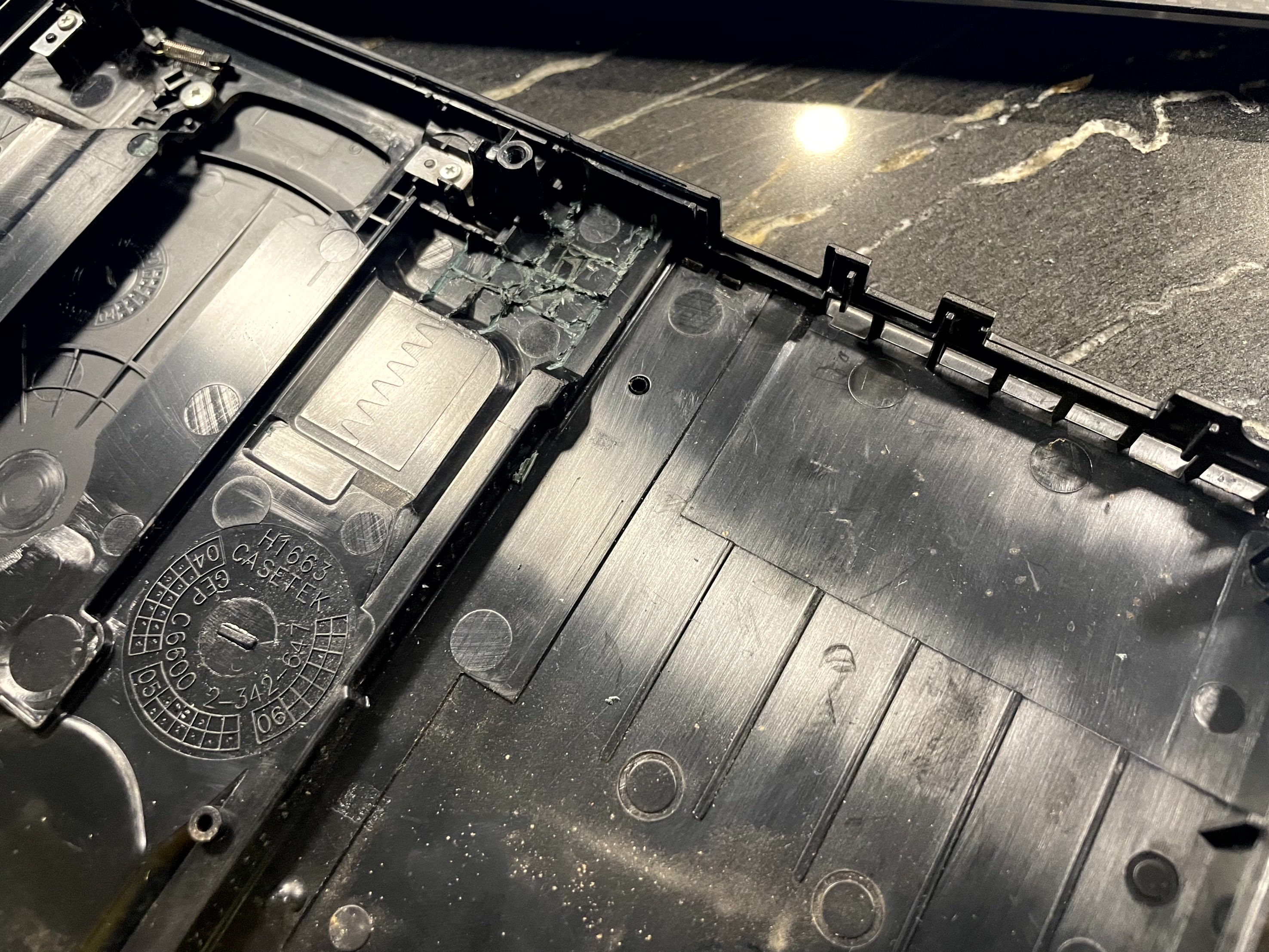
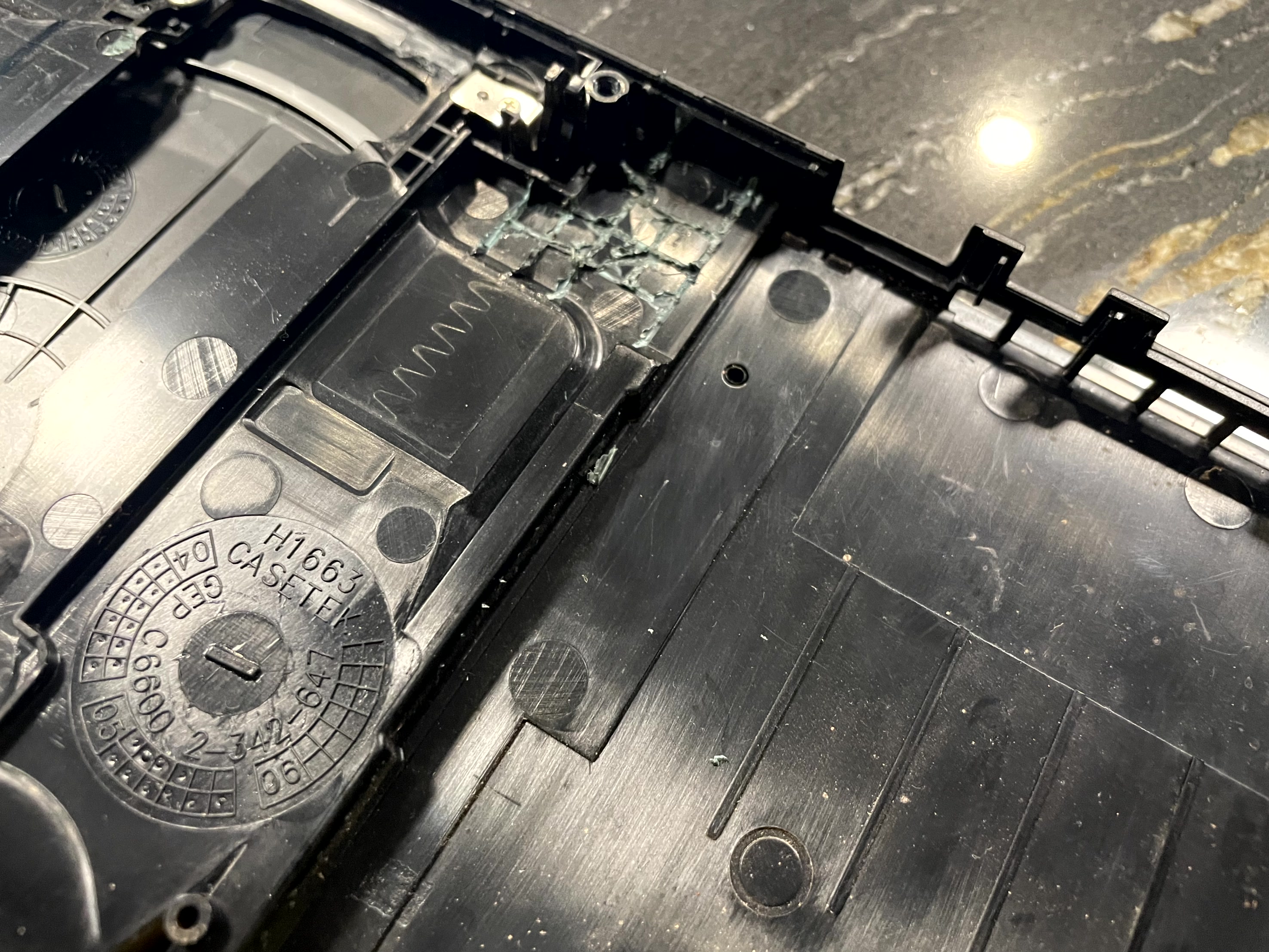
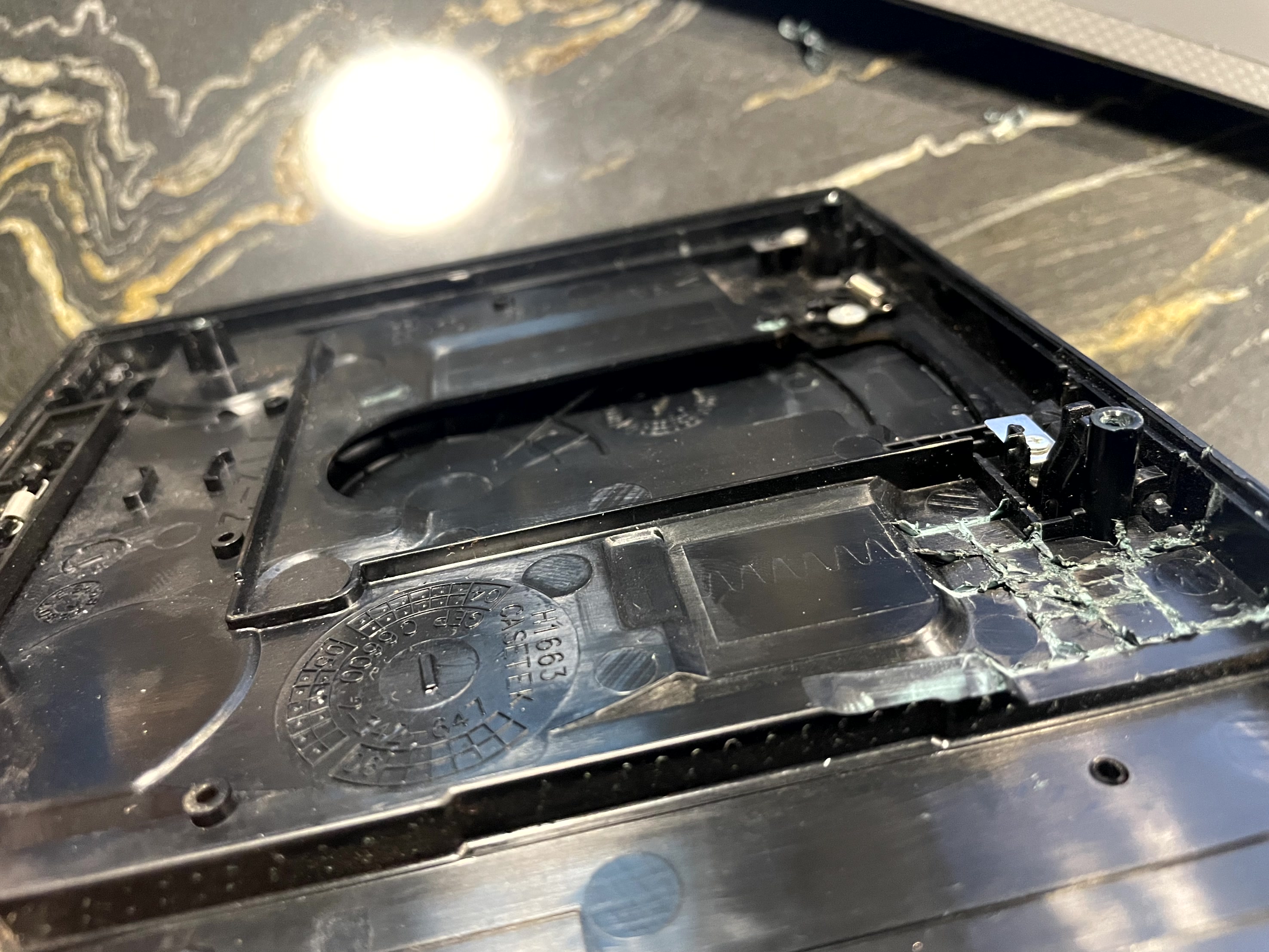
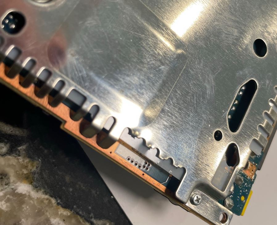
Trim the top Metal Shield in the highlighted area. I use side cutters to make small "fingers" then fatigue the metal off with pliers.
Please choose your installation type:
Slim w/56k modem
Click to expand/collapse
A small amount of trimming needs to be made to the top plastic cover. Trim down the areas highlighted. This doesn't have the 56k cutout in the image, (Just imagine it’s there). Be careful trimming down the area under the DVD drive. Do not trim to far, match the height of the adjacent plastic.
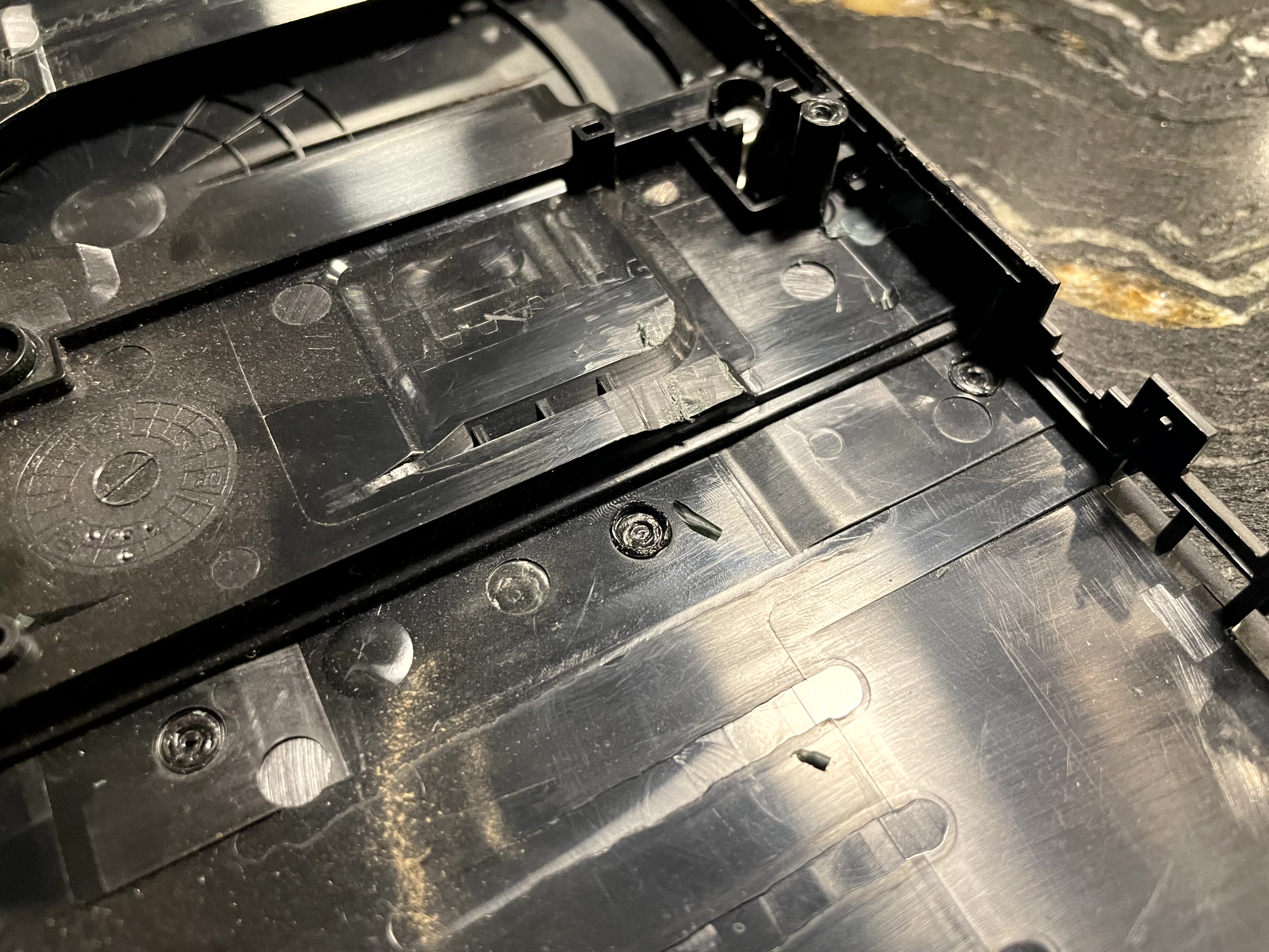
Mount the GEM board to the top shield using the supplied m2 screws. Since this has a 56k Modem there is already a thread for one of the holes. Mount this screw first.
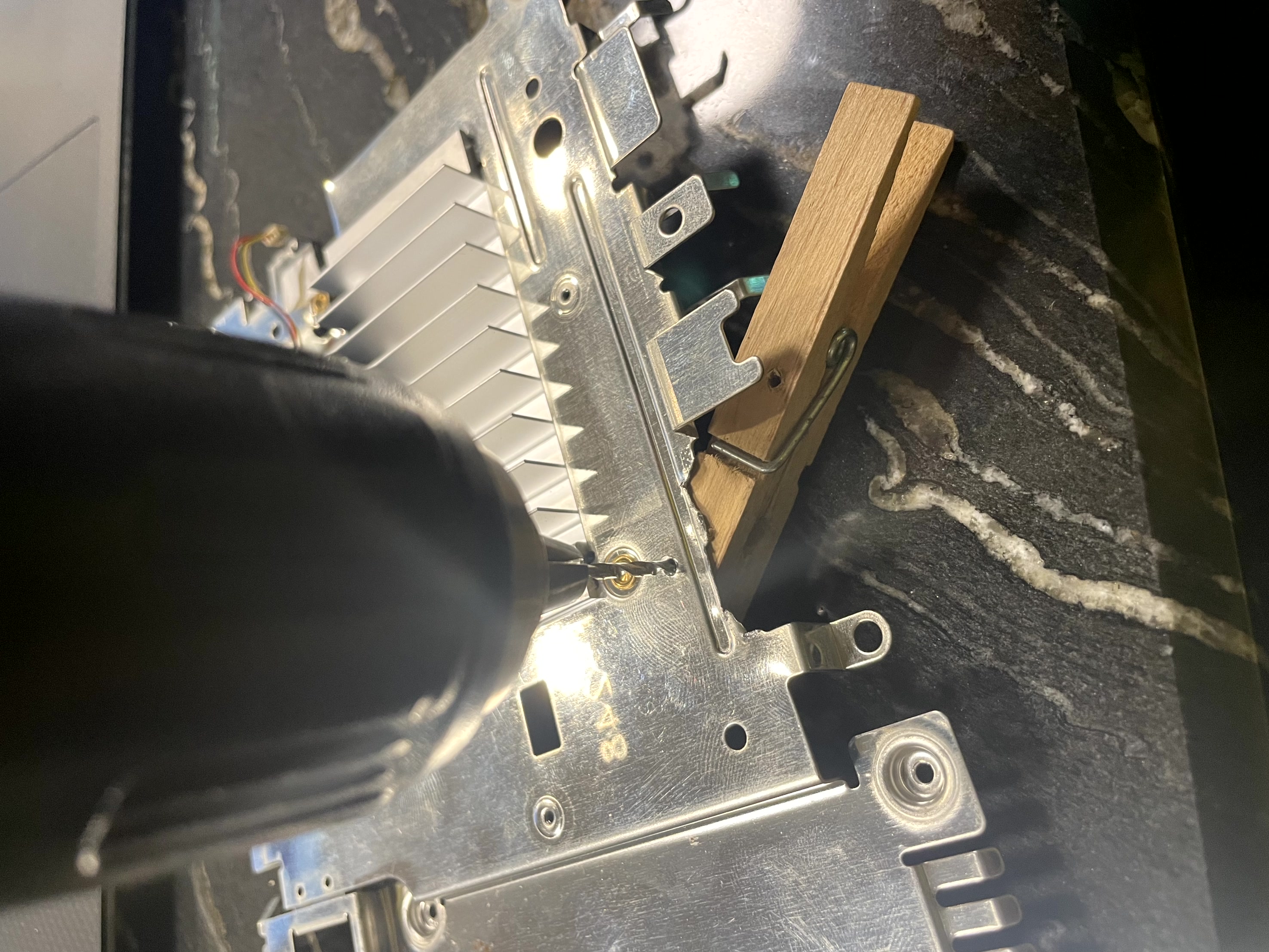
Mark and drill out the other hole with a 2mm drill bit.
- Do not drill the metal shield with the GEM board in place.
- Make sure the bottom of the metal shield is supported with wood when drilling, I use a clothes pin. (This stops the metal from shield from bending during drilling)
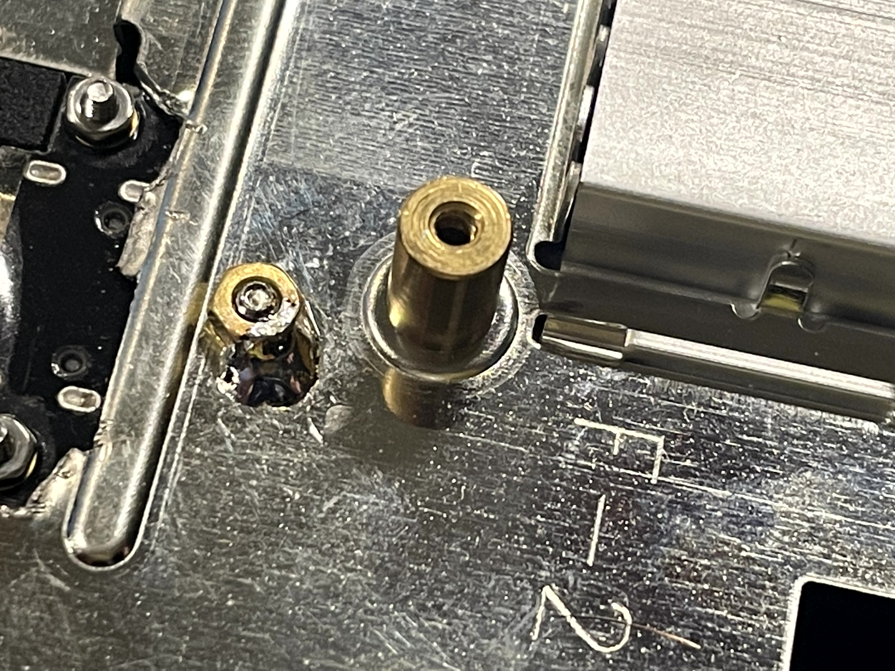
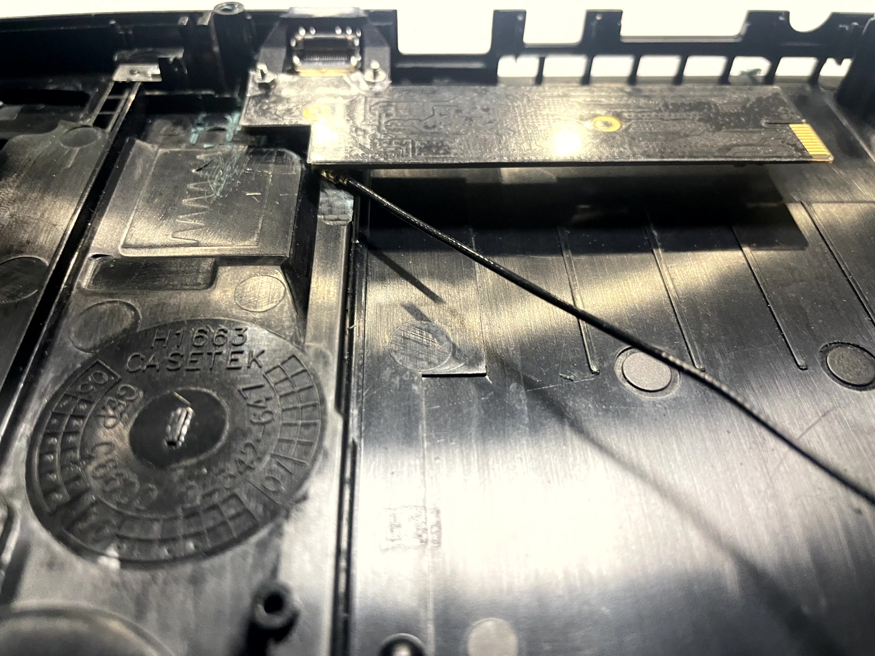
Mount the GEM board back on the metal shield. Use an M2 screw and nut for the new hole. Its recommended you solder the brass nut to the bottom of the metal shield. This will allow you to remove the GEM board without complete disassembly. Do not solder to the screw to the nut.
Proceed to step 2.
Slim NO 56k modem
Click to expand/collapse
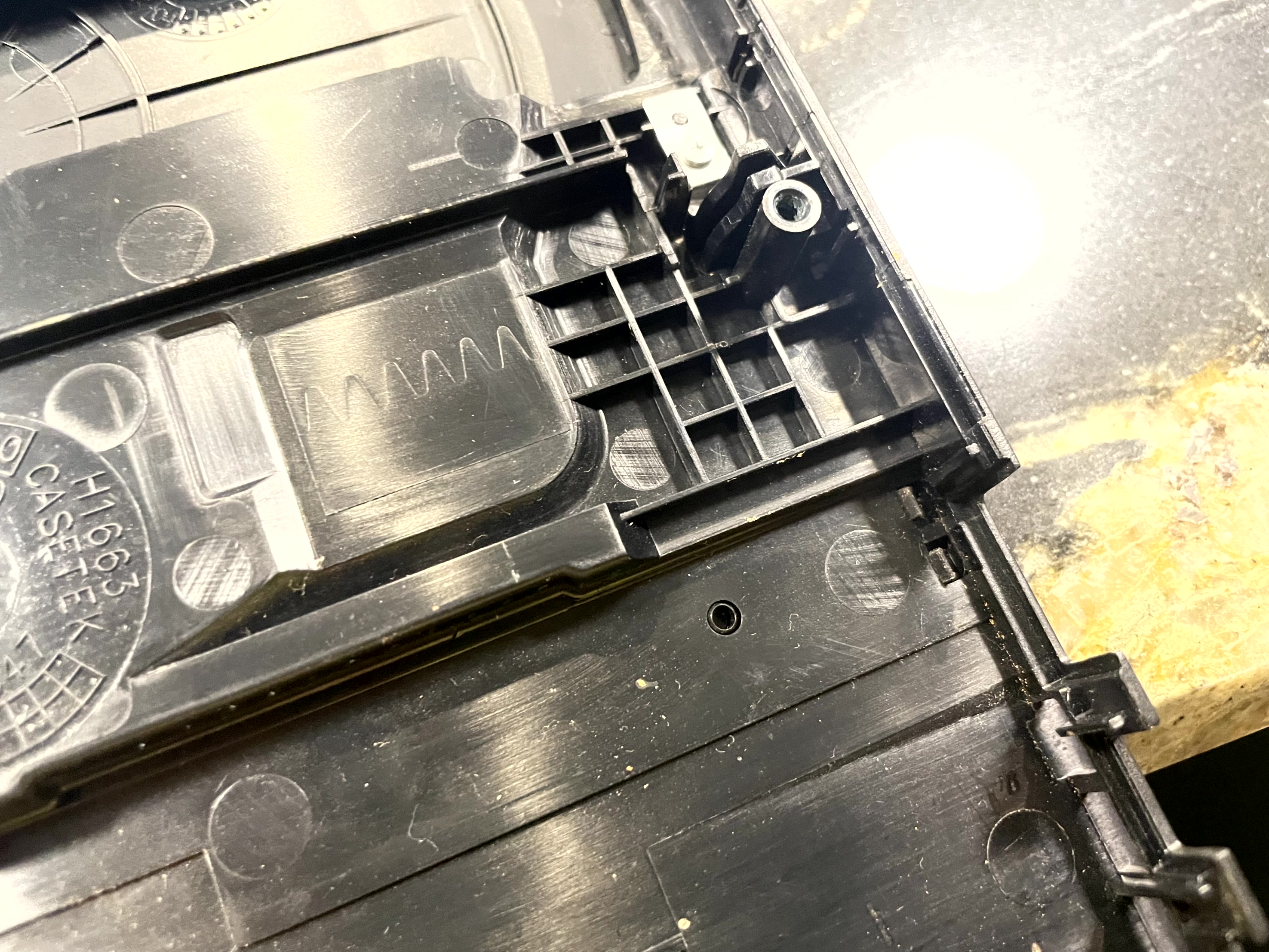
Remove the hdmi faceplate expansion using an exacto knife. Then just fatigue bend the piece off.
If your top case has the webbing as shown please remove it, not all slims have this.
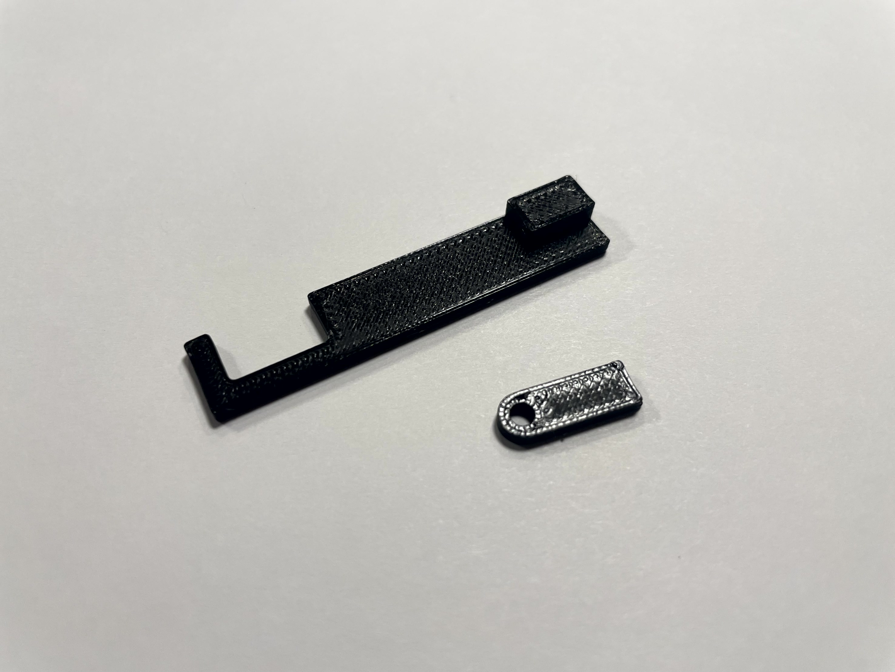
Break apart the 3d printed pieces. Install the cut jig into the TOSLINK port as shown.
The area shown in the jig needs to be removed. Cutting the case will take a while, please be patient. The key to make a good hole is symmetry. The jig cutout is on the tight side, so you will need to make adjustments after the jig is removed.
To perform these cuts I recommend:
- Small plastic Side Cutters (This removes bulk material)
- Small files and exacto knife.
Here is a rough cut, with final cutting still needed.
Start test fitting the GEM, Do not force it, and keep slowing filing and cutting until it can slide down.
Lay the top and bottom plastic cases next to each other. Align these perfectly to each other, and mark the ribbed plastic on the bottom case where it aligns with the GEM HDMI mount on both sides:
After marking, remove the small plastic rib that is between your two marks.
Test fit just the plastic cases with the GEM. You should have something like this. As you can see in my image I need to remove a more material on the top case to so the cases can fit together. This is the time to be extremely precise with the filing and cutting.
We still need to make one smaller trim on the top case, when the antenna is installed it will make contact with the top shield. This area needs to be trimmed. Be extremely careful, as if you cut too deep you will go through the case. You will only be removing a around 1mm-1.5mm. Match the height to the adjacent plastic.
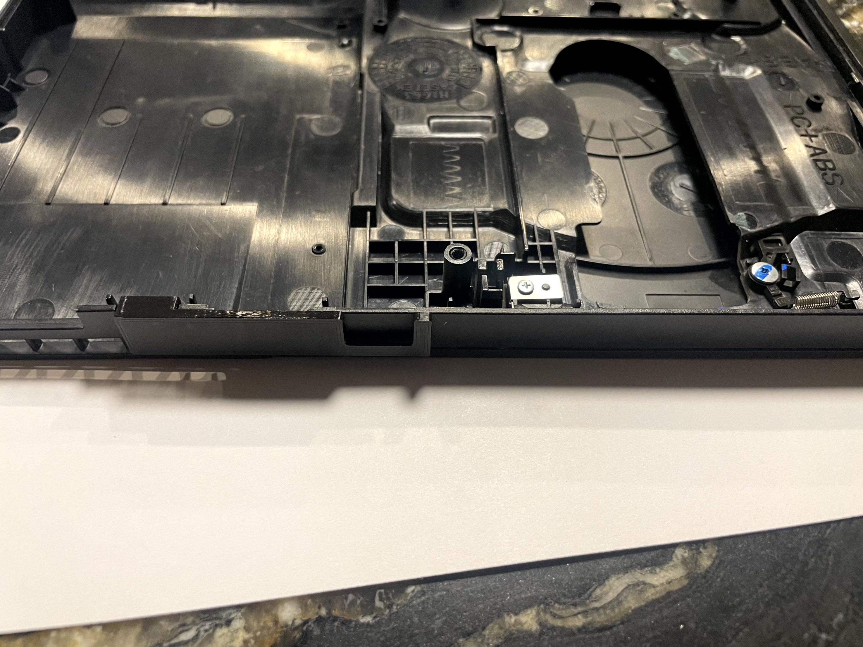
The next step is to secure the GEM board to the top metal shield. Reintall the bottom shield, motherboard and top shield into the bottom case. You will have marks cut where the GEM board will sit in the bottom case. Test fit the GEM board, make sure you like the fitment. Trim and adjust if needed. Some top metal shields have a mounting hole that is already threaded. Use this hole and secture the GEM board.
Once you are satisfied. You need to make two marks (Assuming you do NOT have the factory hole) on the metal shield through the large mounting holes. Try to be delicate if the GEM board moves or your drill holes are off the GEM board will not line up to the case cut you made when you reassemble.
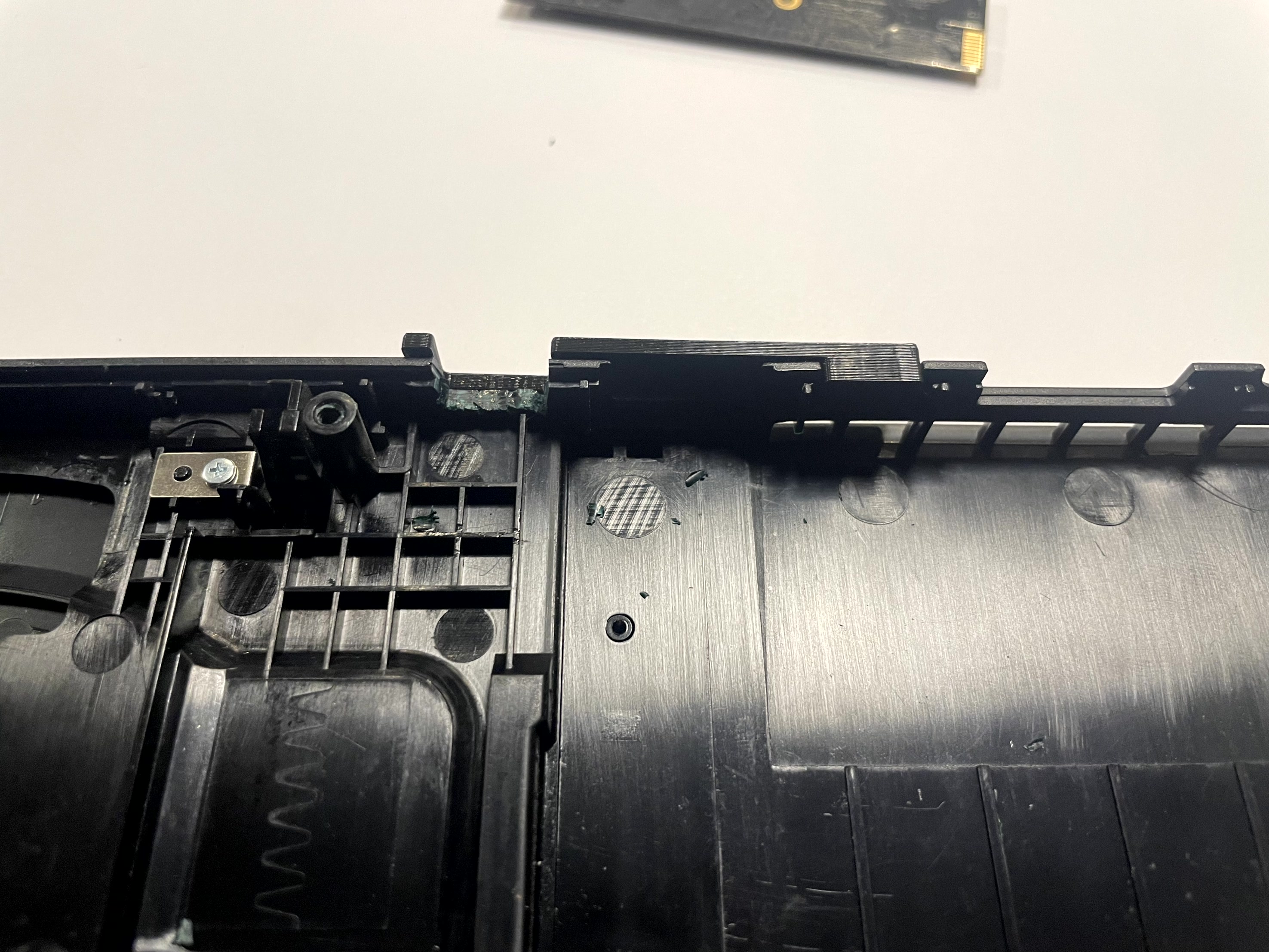
After marking the metal shield remove the GEM and drill out the one or two holes using an 2MM drill bit. Use some type of wood below the metal shield when drilling as this will stop the shield from bending. I use a clothes pin
After drilling, mount the GEM board with the supplied M2 Screws and Nuts. Do a test fitment with the antenna installed. Make sure you like how the HDMI port looks when both cases are together etc. Once satisfied solder the the brass nuts to top metal shield.
Proceed to Step 2.
Step 1b - Mounting the GEM board (79K)
Click to expand/collapse
The 79K is different enough to needs its own mount section.Remove the hdmi faceplate expansion using an exacto knife. Then just fatigue bend the piece off.
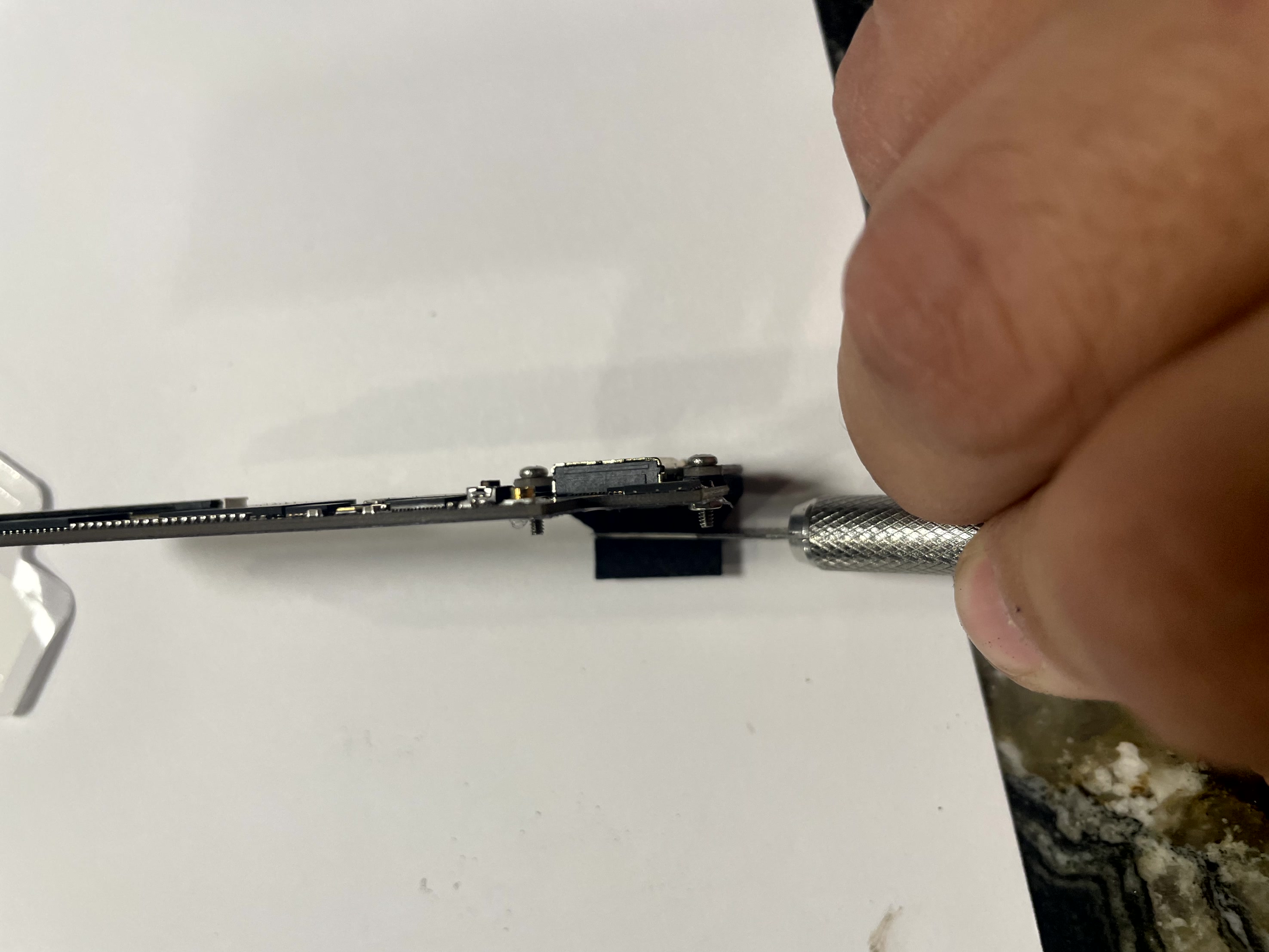
Assemble the HDMI Mount by first installing the FFC cable into the PCB
If your top case has the webbing as shown please remove it, not all slims have this.
Break apart the 3d printed pieces. Install the cut jig into the TOSLINK port as shown.
The area shown in the jig needs to be removed. Cutting the case will take a while, please be patient. The key to make a good hole is symmetry. The jig cutout is on the tight side, so you will need to make adjustments after the jig is removed.
To perform these cuts I recommend:
- Small plastic Side Cutters (This removes bulk material)
- Small files and exacto knife.
Here is a rough cut, with final cutting still needed.
Start test fitting the GEM, Do not force it, and keep slowing filing and cutting until it can slide down.
Lay the top and bottom plastic cases next to each other. Align these perfectly to each other, and mark the ribbed plastic on the bottom case where it aligns with the GEM HDMI mount on both sides:
After marking, remove the small plastic rib that is between your two marks.
Test fit just the plastic cases with the HDMI MOUNT. You should have something like this. As you can see in my image I need to remove a more material on the top case to so the cases can fit together. This is the time to be extremely precise with the filing and cutting.
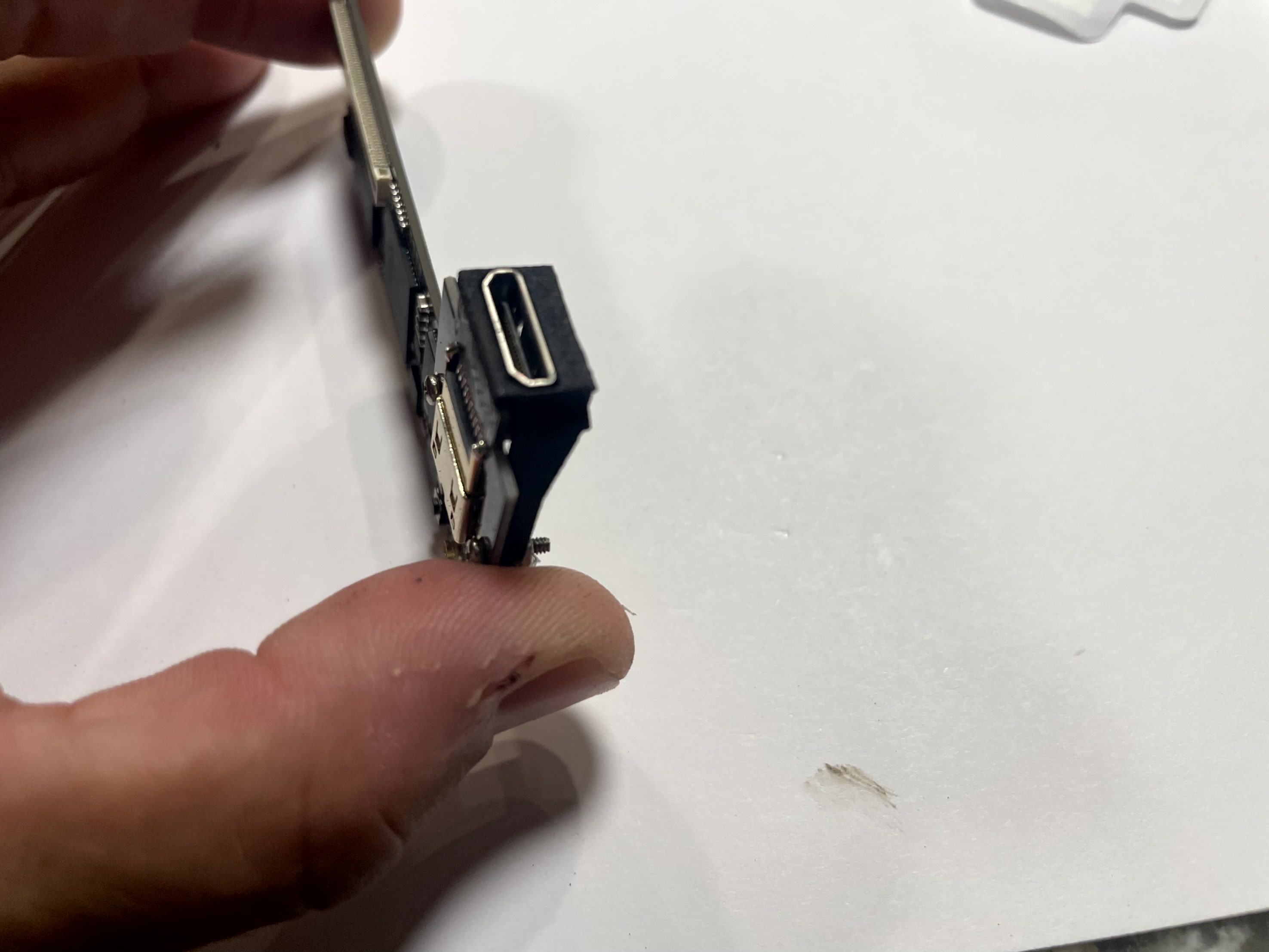
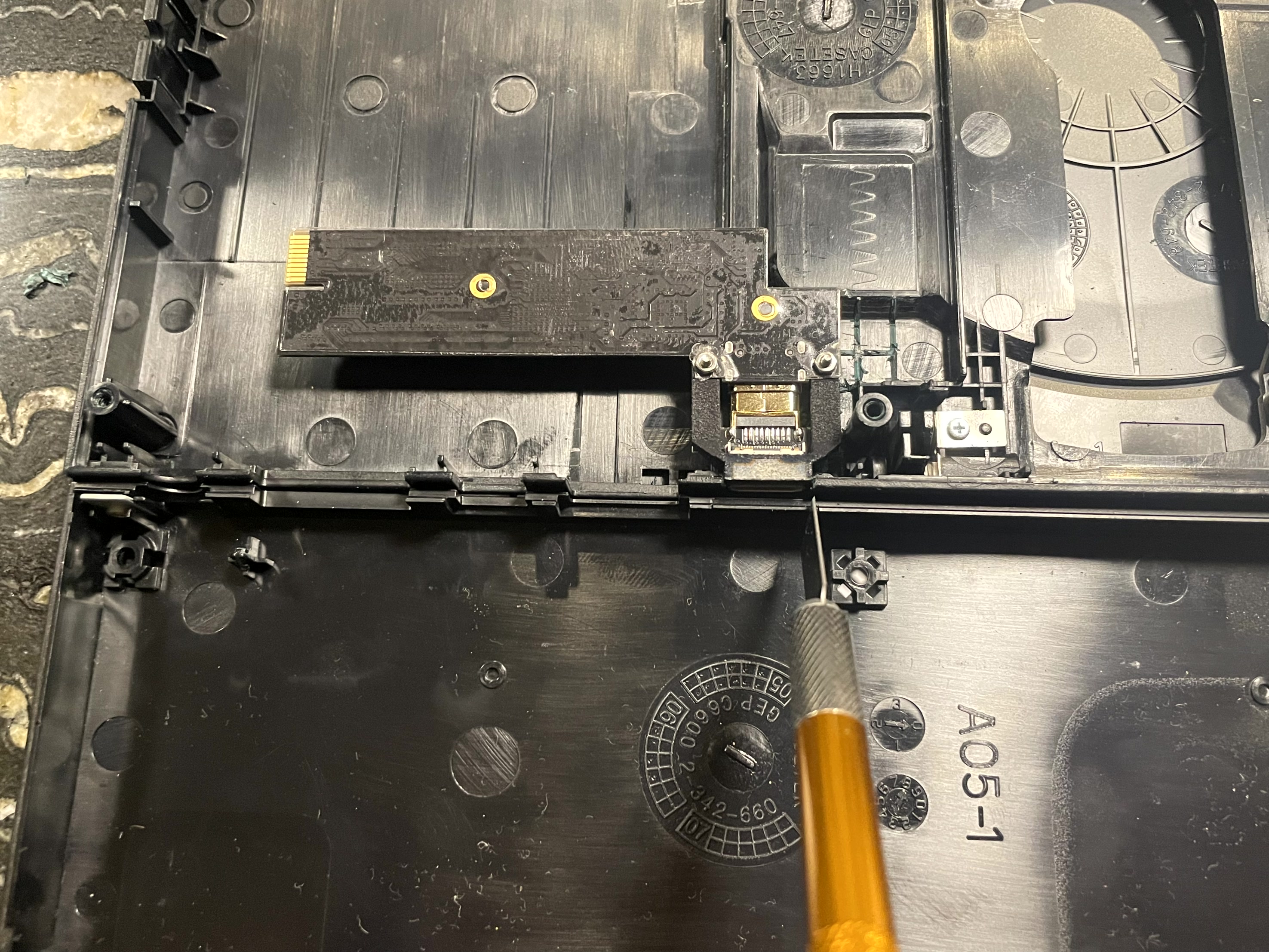
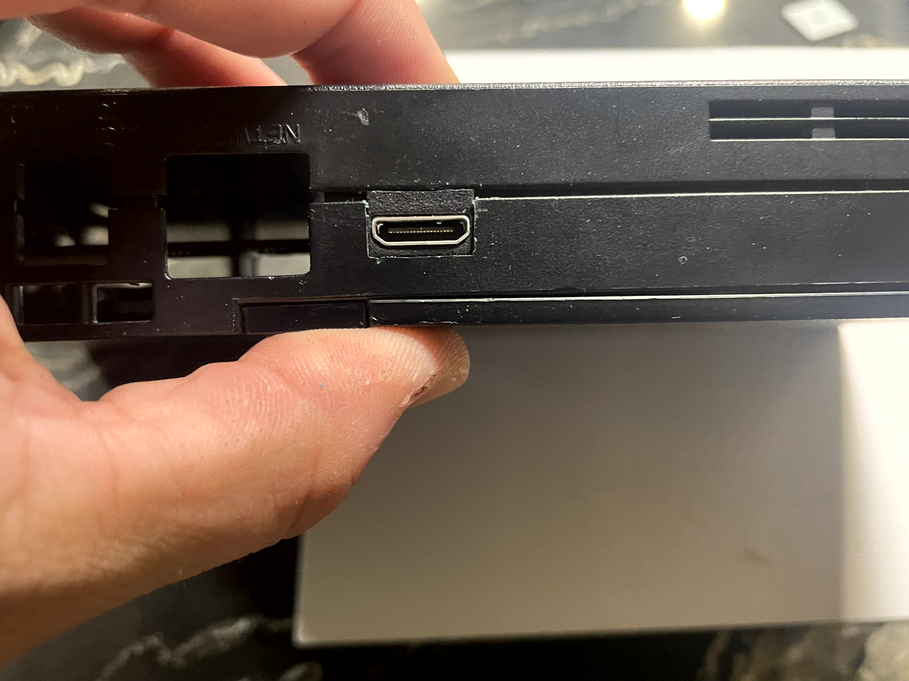
After the HDMI hole is cut its time to mount the HDMI mount permentaly to the metal shield. Make sure this is aligned, then mark and drill the holes. DO NOT DRILL into the motherboard.
After drilling use the M2 screw and brass nuts to mount the HDMI.
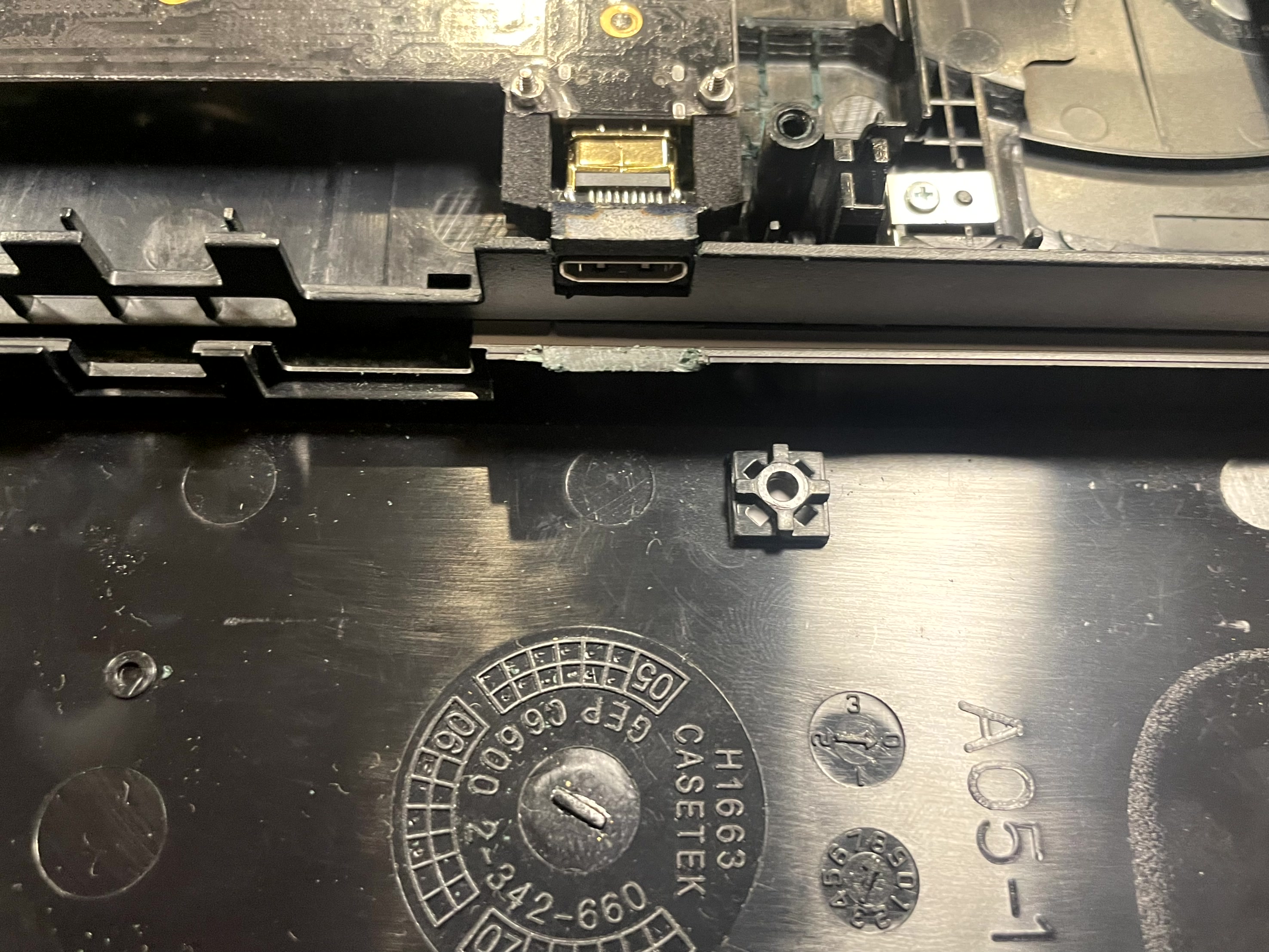
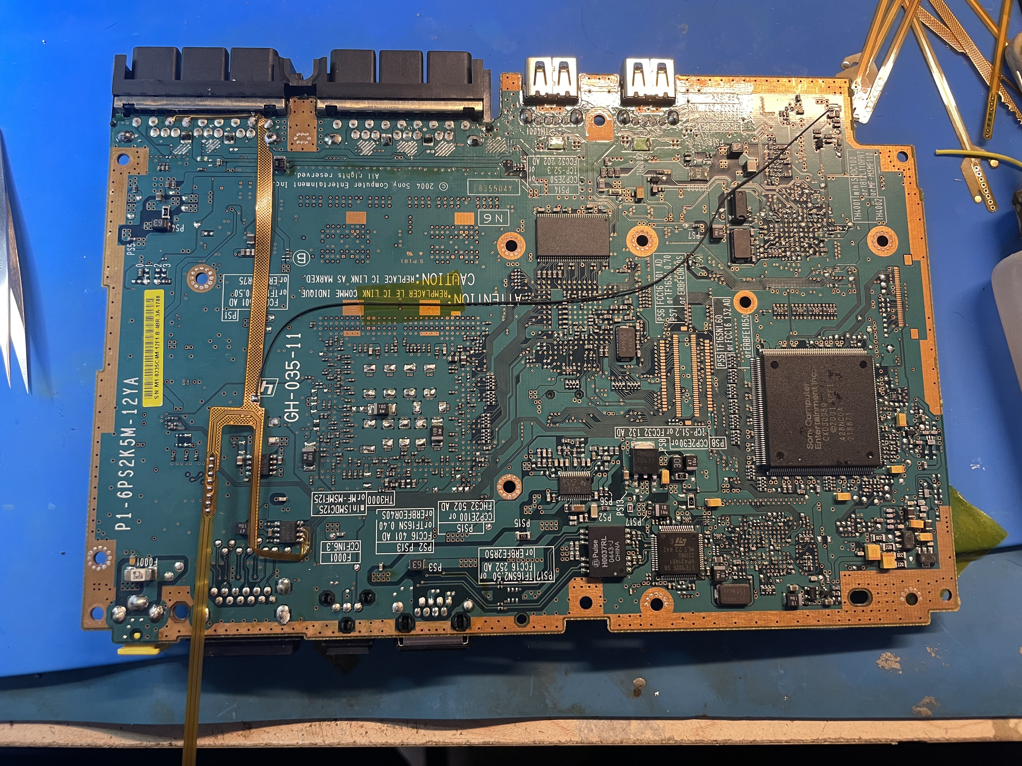
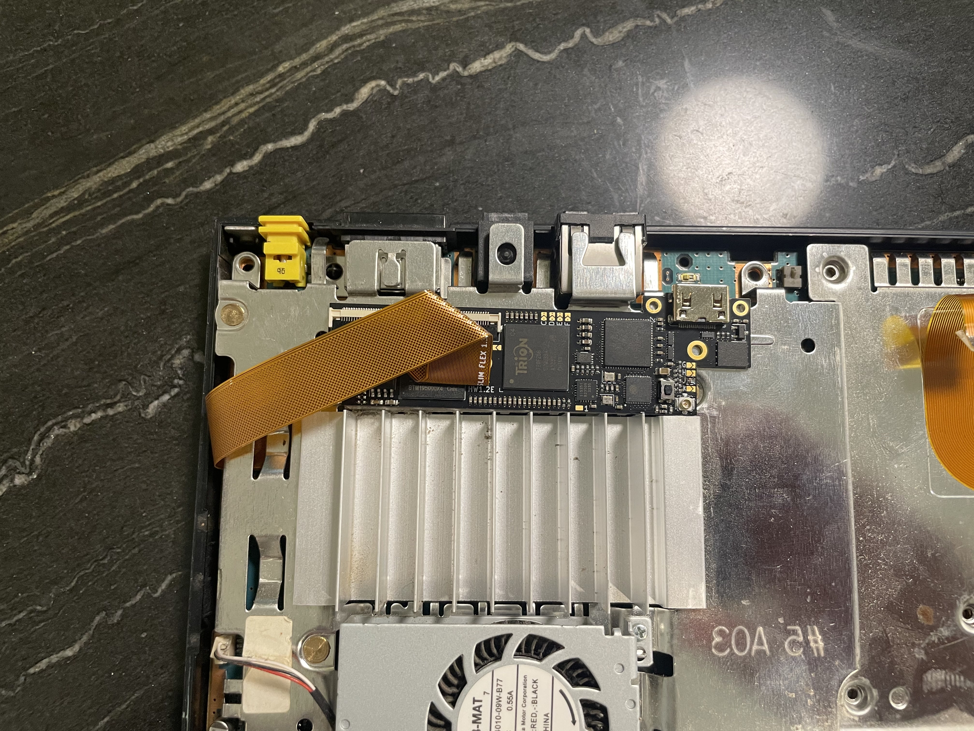
DO NOT mount the GEM board yet using the M2 screws. We will drill these holes last after confirming the main flex aligns. You should have something that looks like this at this point.
Step 2 - Installing the controller/audio hookup.
Click to expand/collapse
All slims models (up to 79xxx) have the same controller and audio hookups.
Install the flex as shown, be extremely gently. Also pay attention to which side faces up.
Bend the flex end and solder the other 3 locations
Slim Pre 79K
Click to expand/collapse
Hold the flex as shown and solder to the leg of the audio chip. Bend the flex slightly so it lays flat.
The controller, audio and reset lines can also be used with wires. Refer to the pinouts for this information. https://docs.pixelfx.co/GEM-Pinouts.html
Slim 79K
Click to expand/collapse
Route the audio leg to through the hole. Isolate the cable with kapton tape.
The controller, audio and reset lines can also be used with wires. Refer to the pinouts for this information. https://docs.pixelfx.co/GEM-Pinouts.html
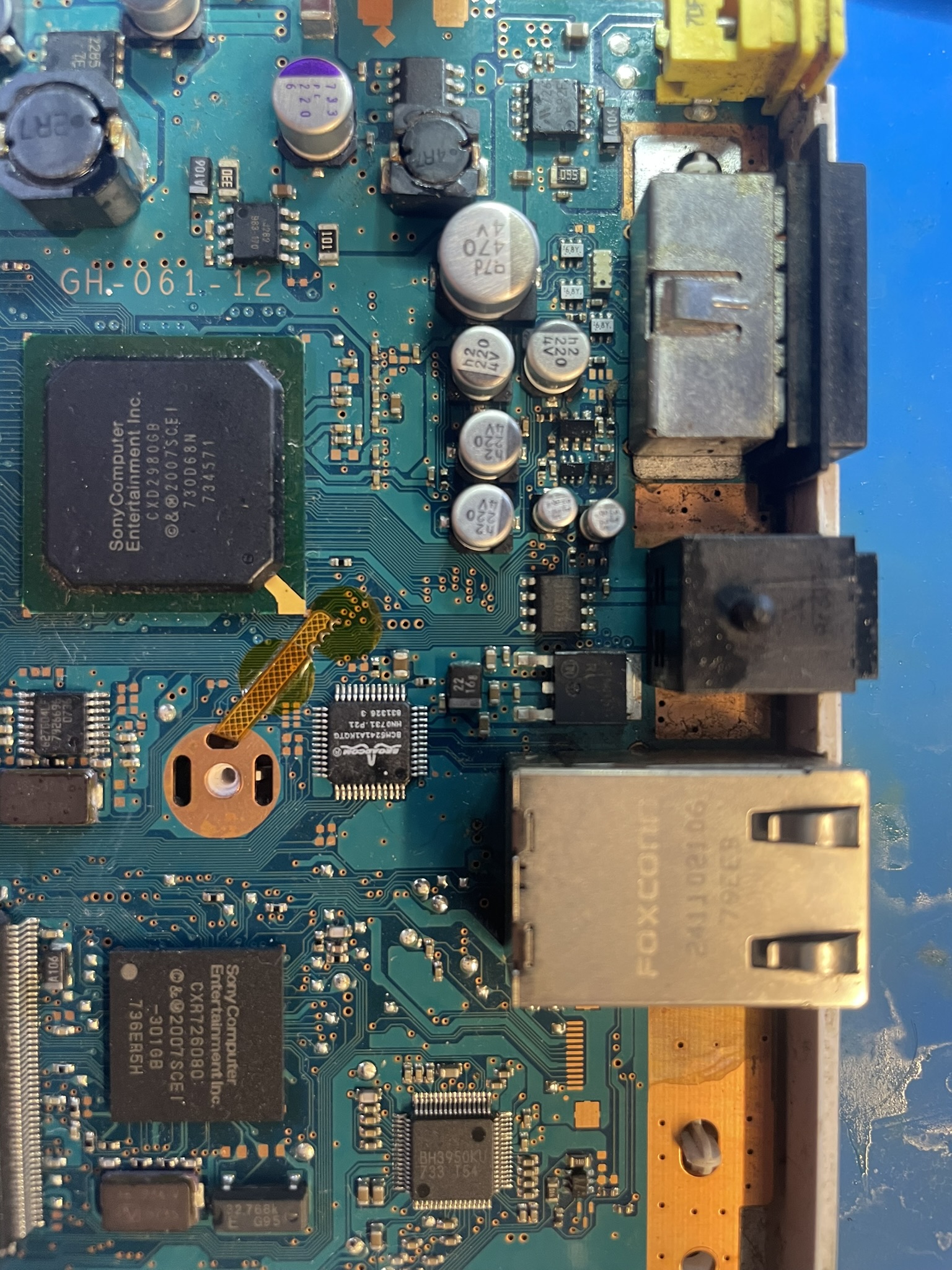
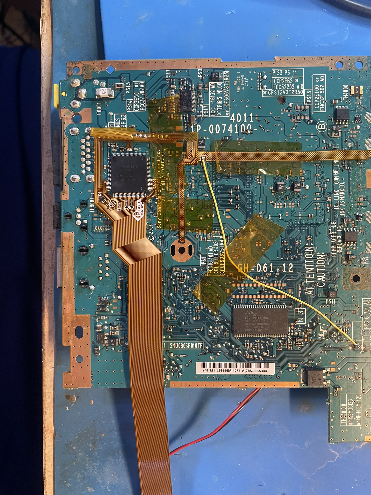
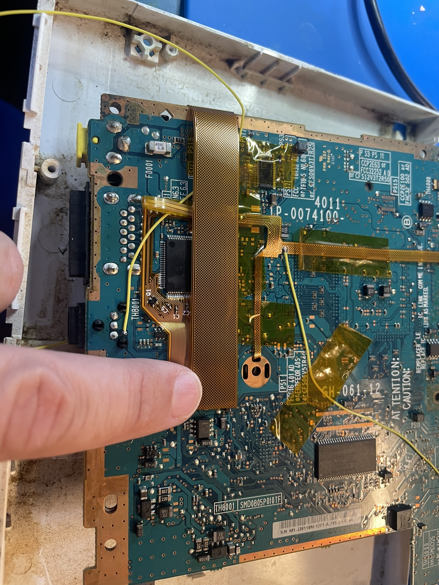
Step 3 - Installing the spdif hookup.
Click to expand/collapse
DTS and Dolby digital audio needs an extra wire routed to the GEM board. If you are not concerned with these modes, then this step is optional.
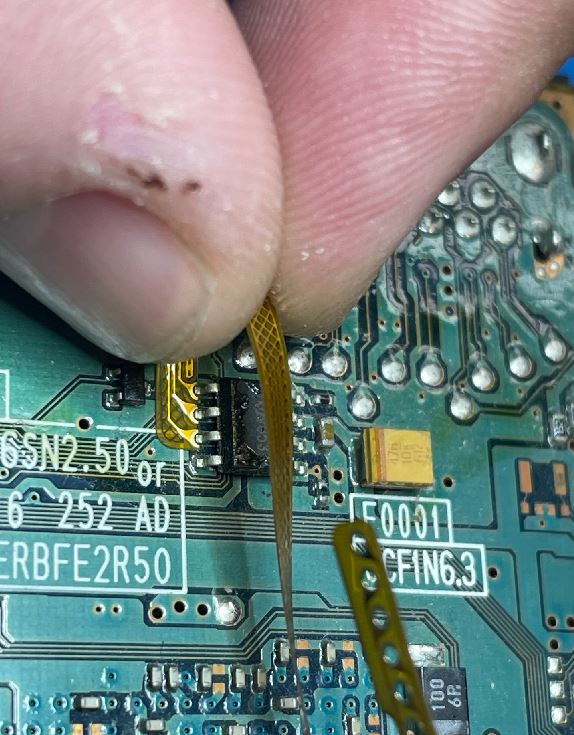
Solder a 6in wire to the SPDIF data pin as shown: (30 AWG is preferred)
THe other end of the wire will be installed once the GEM board is mounted as shown step 6.
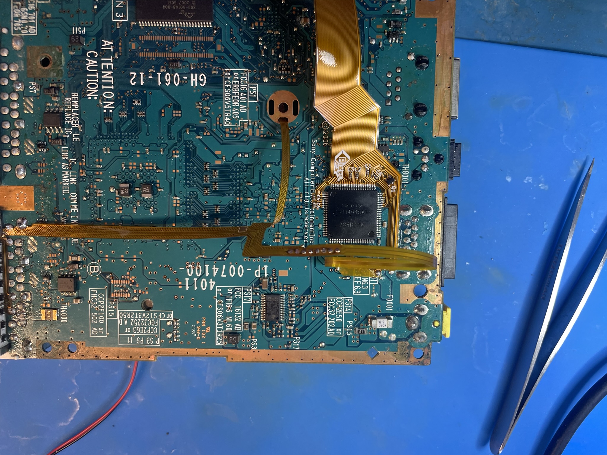
Step 4 - Installing the main flex
Click to expand/collapse
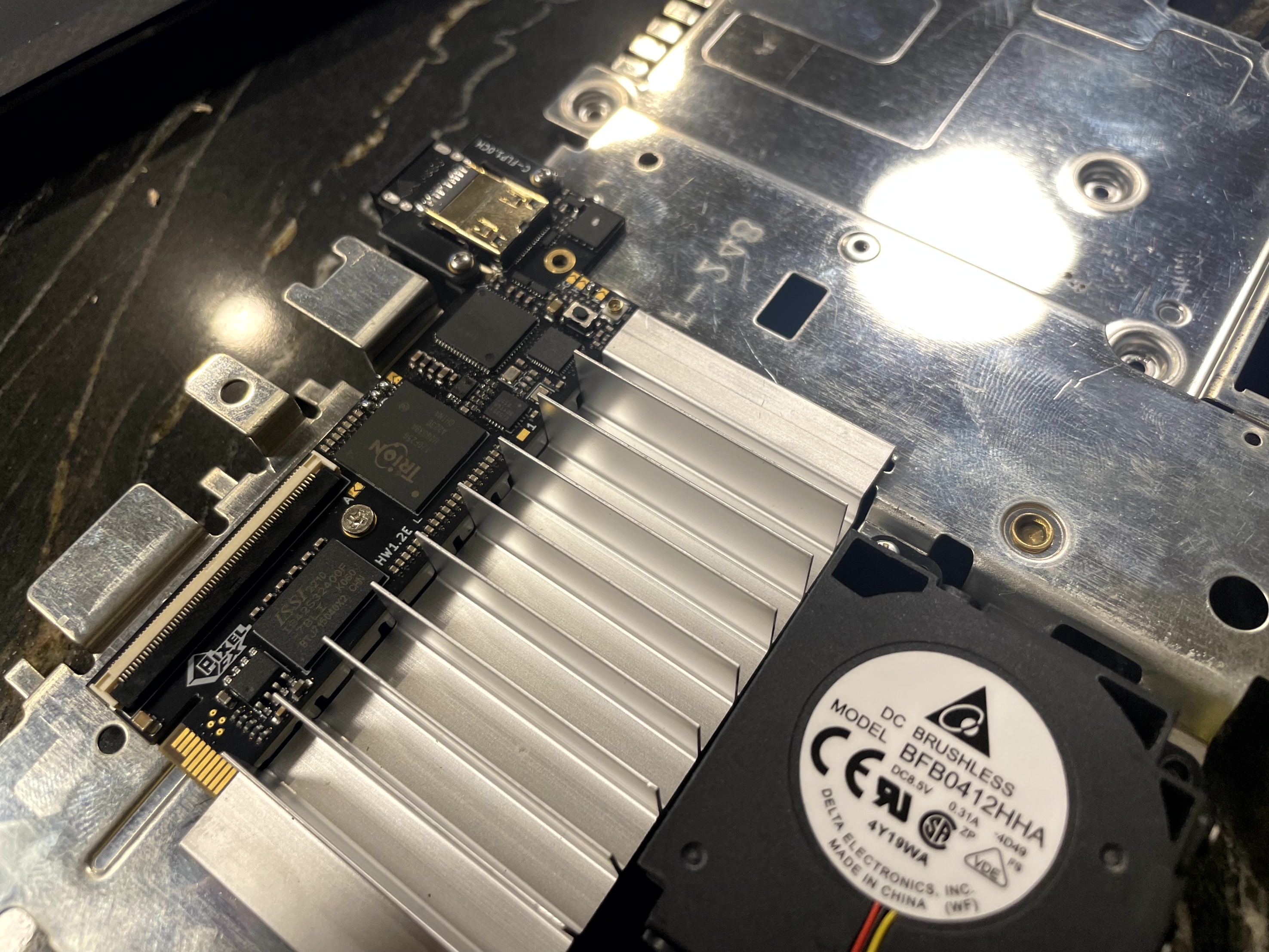
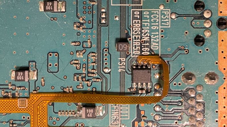
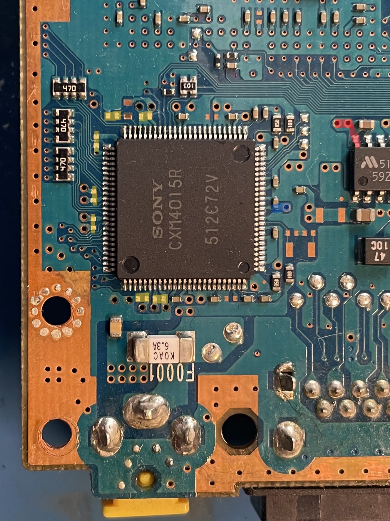
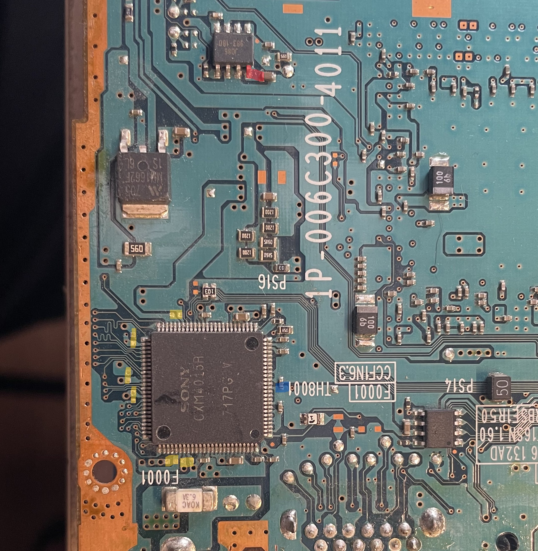
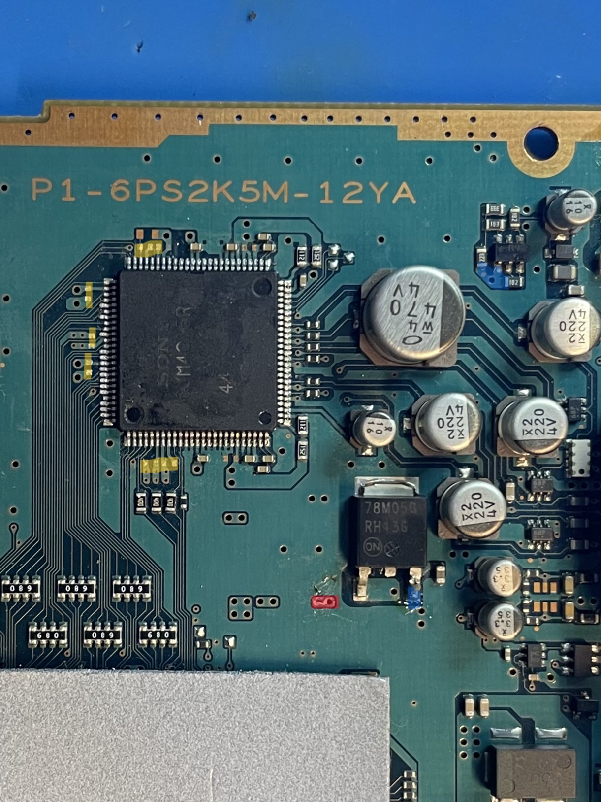
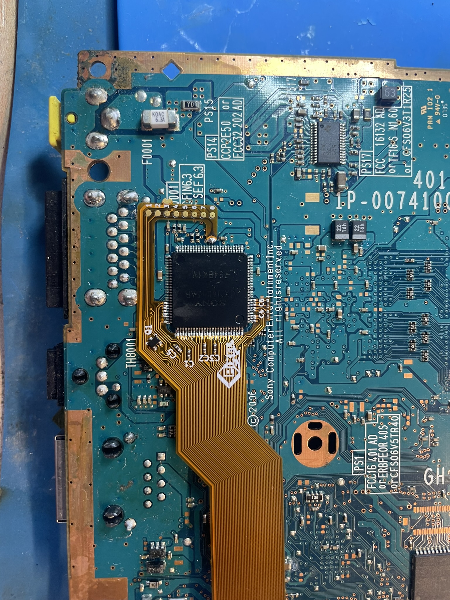
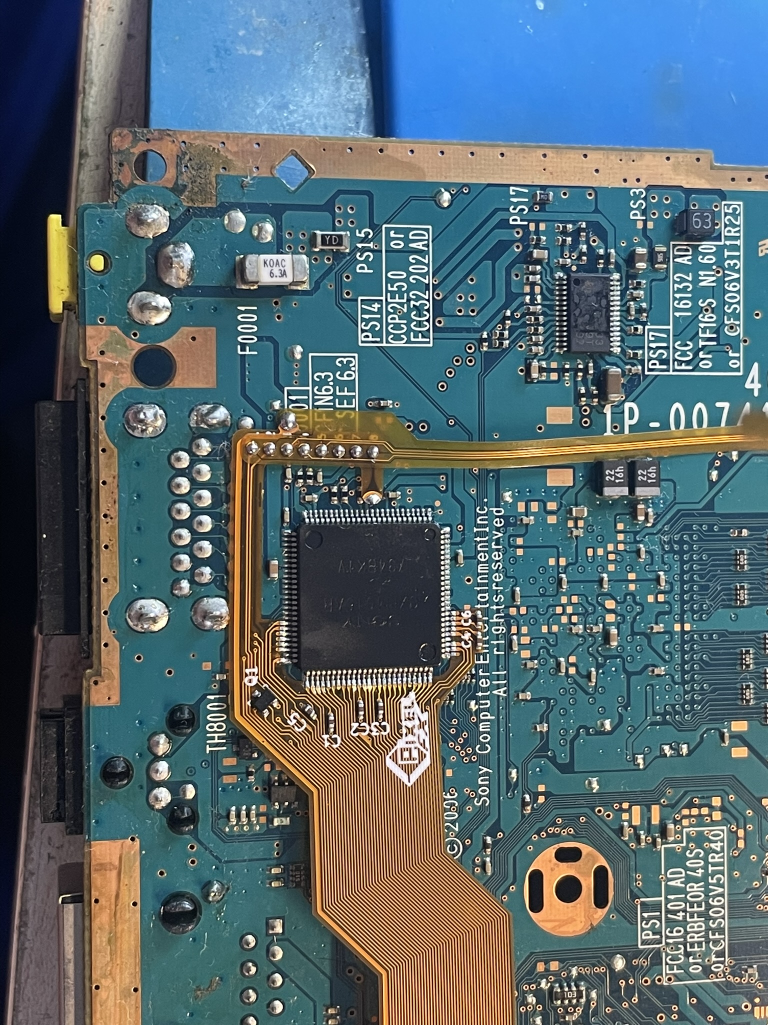
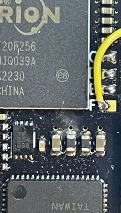
There are 4 main PCB revisions in terms of the video hookups.
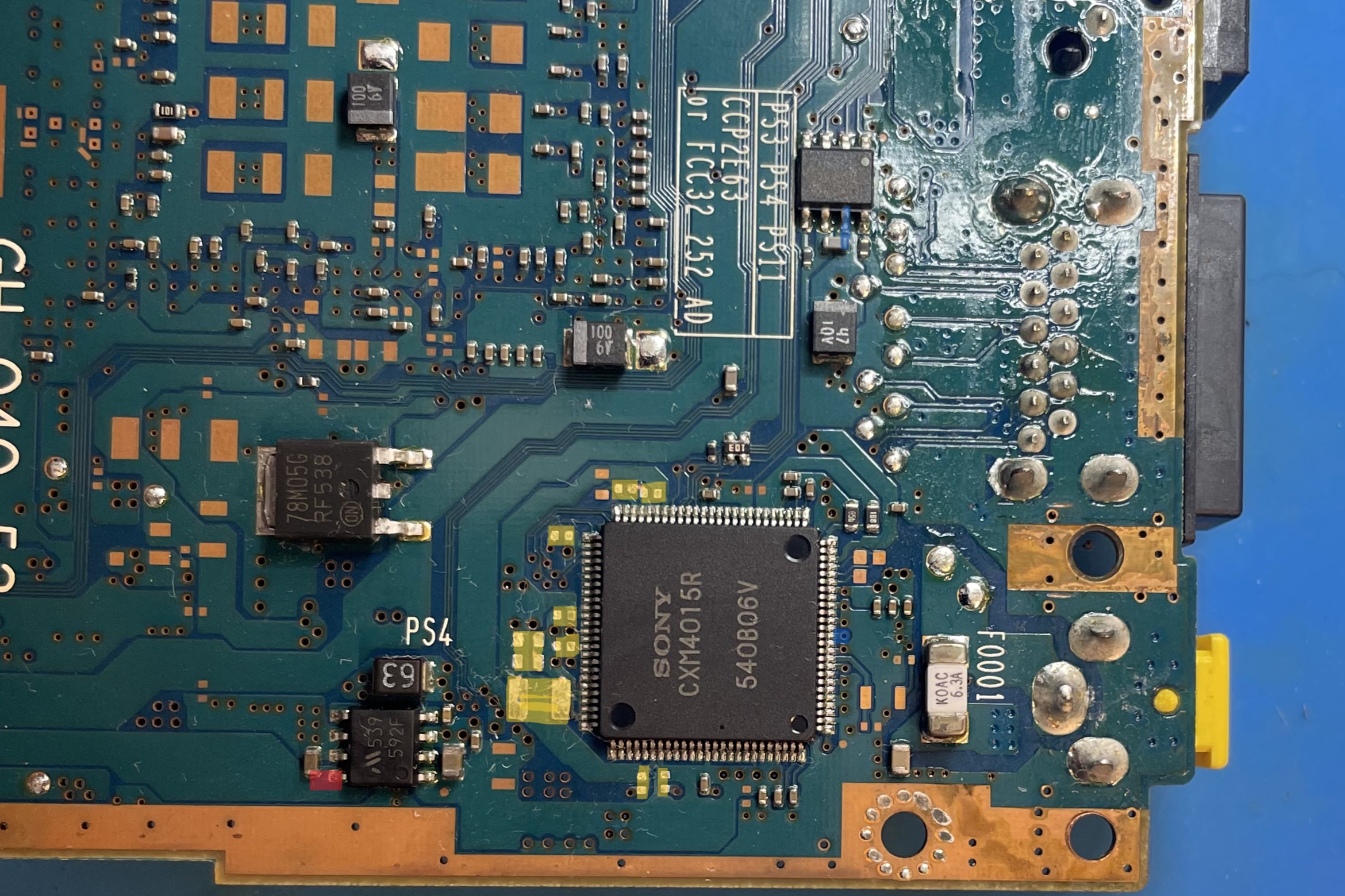
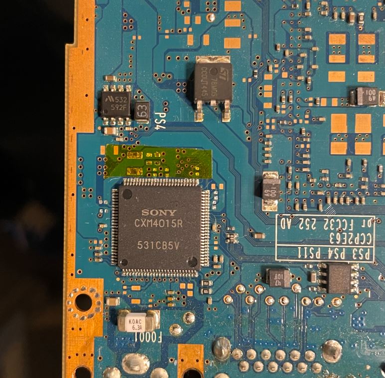
The fastest way to tell is to locate the CMX40xx. This is connected to the GPU video bus.
This chip can be located:
- Top Side
- Bottom Side
- Rotated Bottom Side
- 79K
Top Side and Rotated Bottom side will require the use of the smaller intermediate flex.
Use the following pictures to ID your type. Just look at the orientation and location of the CMX4015 IC compared to your main board.
5v can be found on pin 13 of the CMX40xx
3.3V can be found on pin 8 of 592F (Has an M logo on the chip as well)
These are documented in the images below, but it’s good to know this information.
Select your main board type:
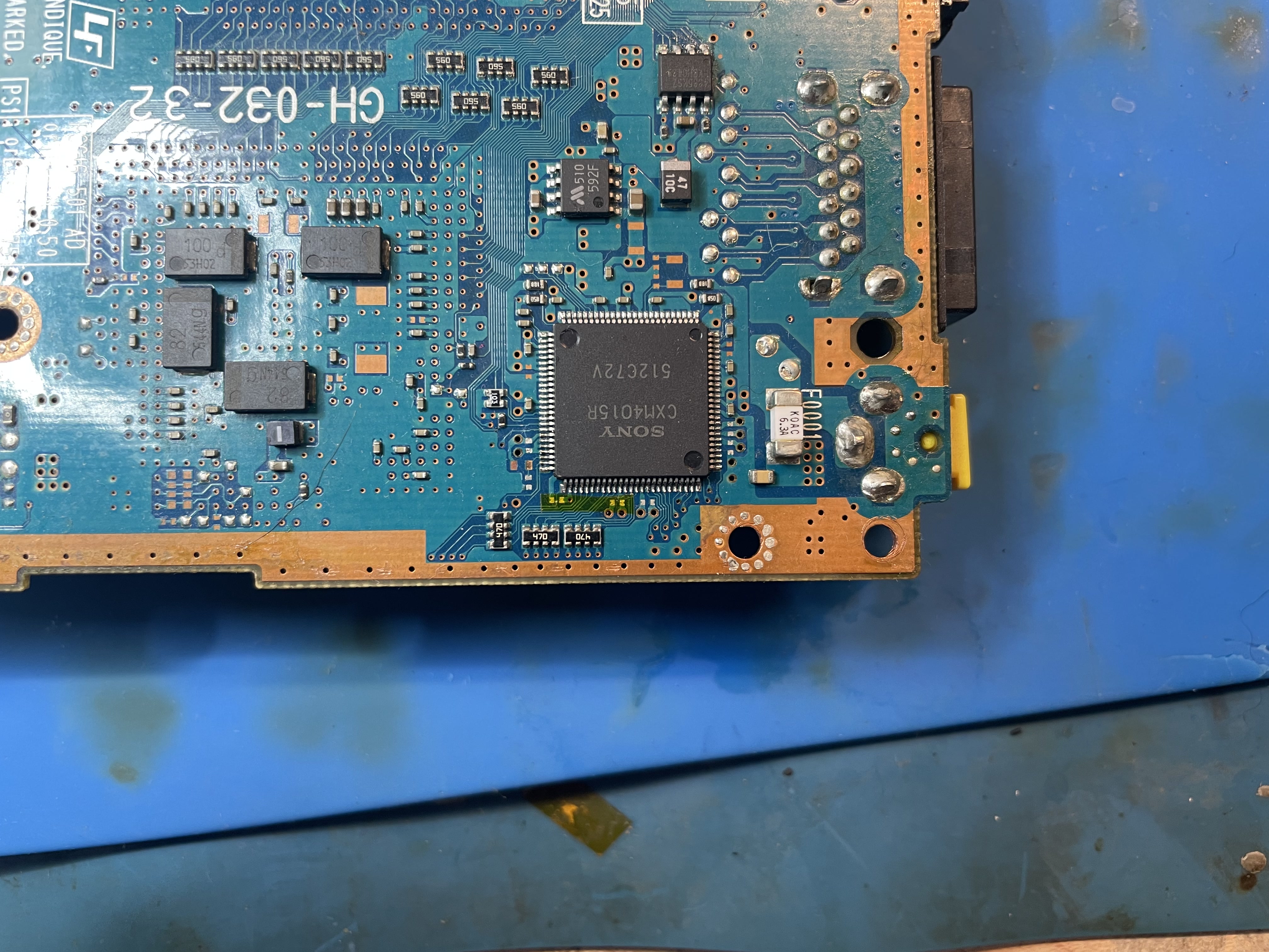
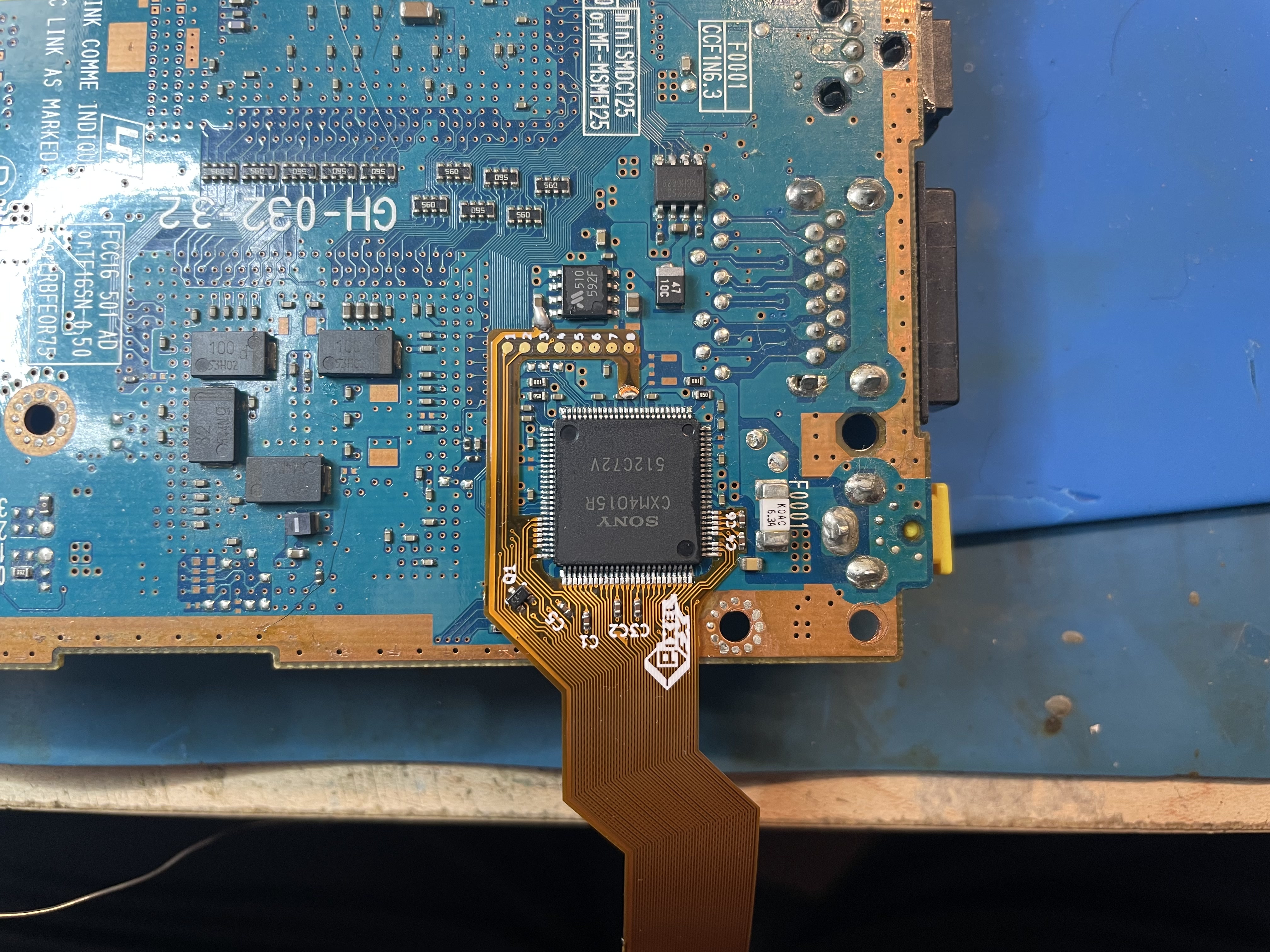
Bottom Side
Click to expand/collapse
This the eaiser to install as it does not require the intermediate flex. I have only seen these two different variants of the bottom side. Choose the mainboard that that matches yours. If you are unsure or need please send me a message.
- Remove the components in yellow.
- Red is 3.3v hookup (Pin 8 592F)
- Blue is 5v hookup (Pin 13 of CMX40xx)
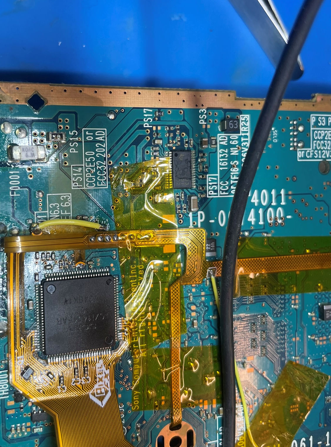
Isolate any pads that might interfere with kapton tape (pads that are extremely close to the CMX40xx)
It is highly recommend you use lead free solder. The solder used in the PS2 has tin which can create micro cracks if leaded soldered is used and not mixed well. If you prefer to use leaded solder you need to wash the pins (mix) or remove the lead free solder all together. After installing many kits I personally prefer to just use lead free.
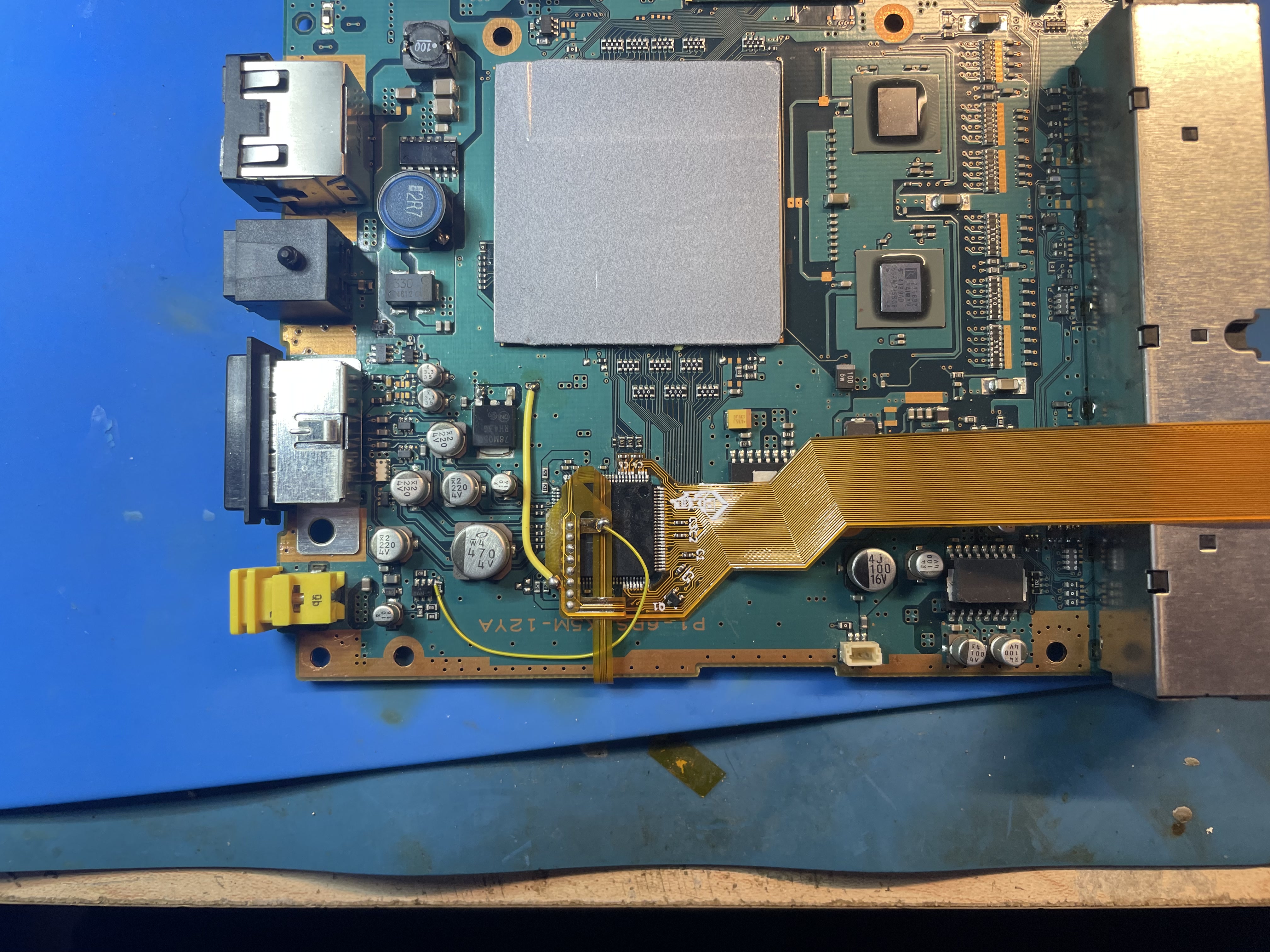
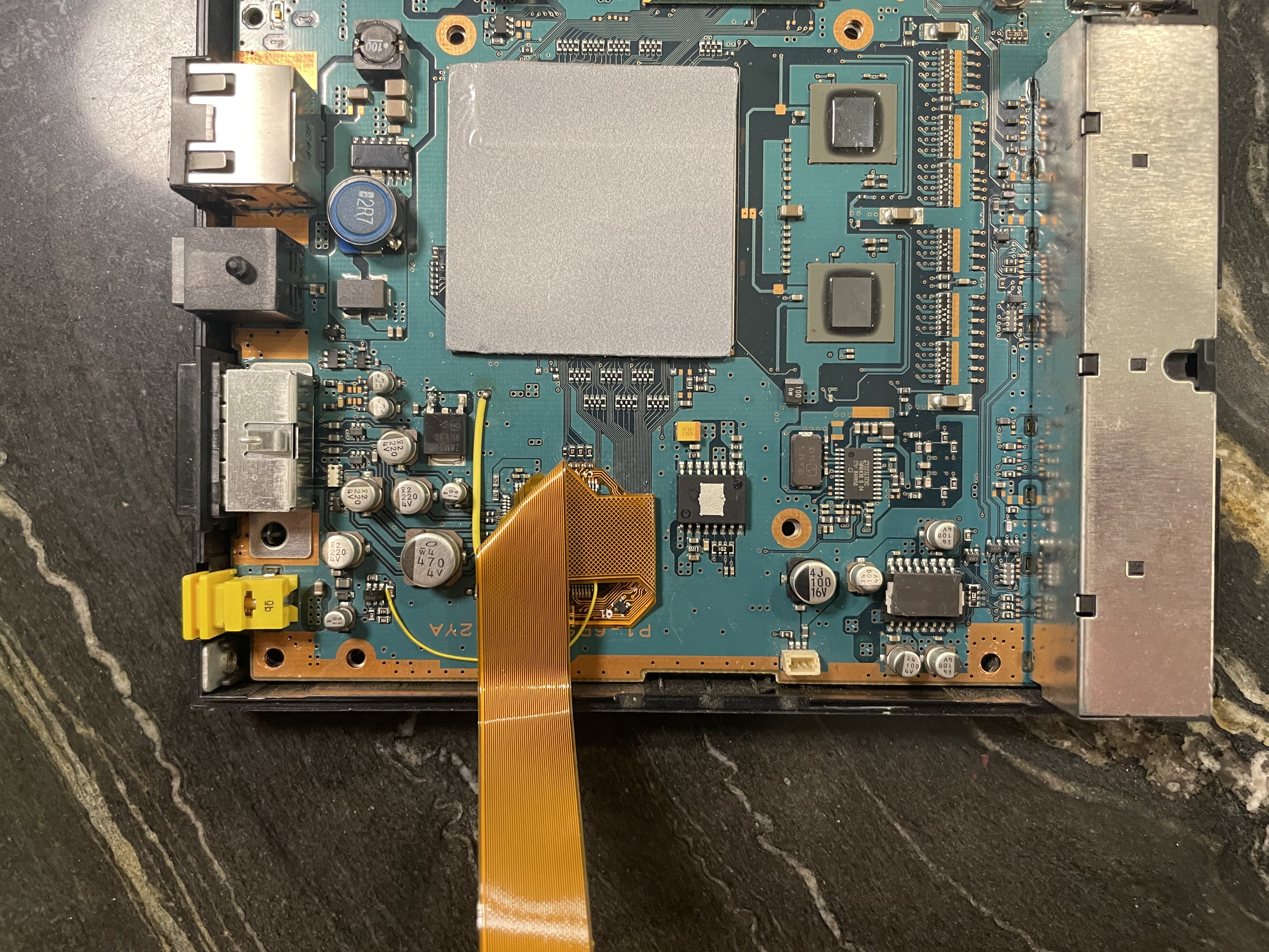
Install the main flex: PAY ATTENTION TO THE 5V and 3.3V HOOKUPS
- Solder the controller/audio flex to the main flex
- Solder the reset wire to the controller/audio flex
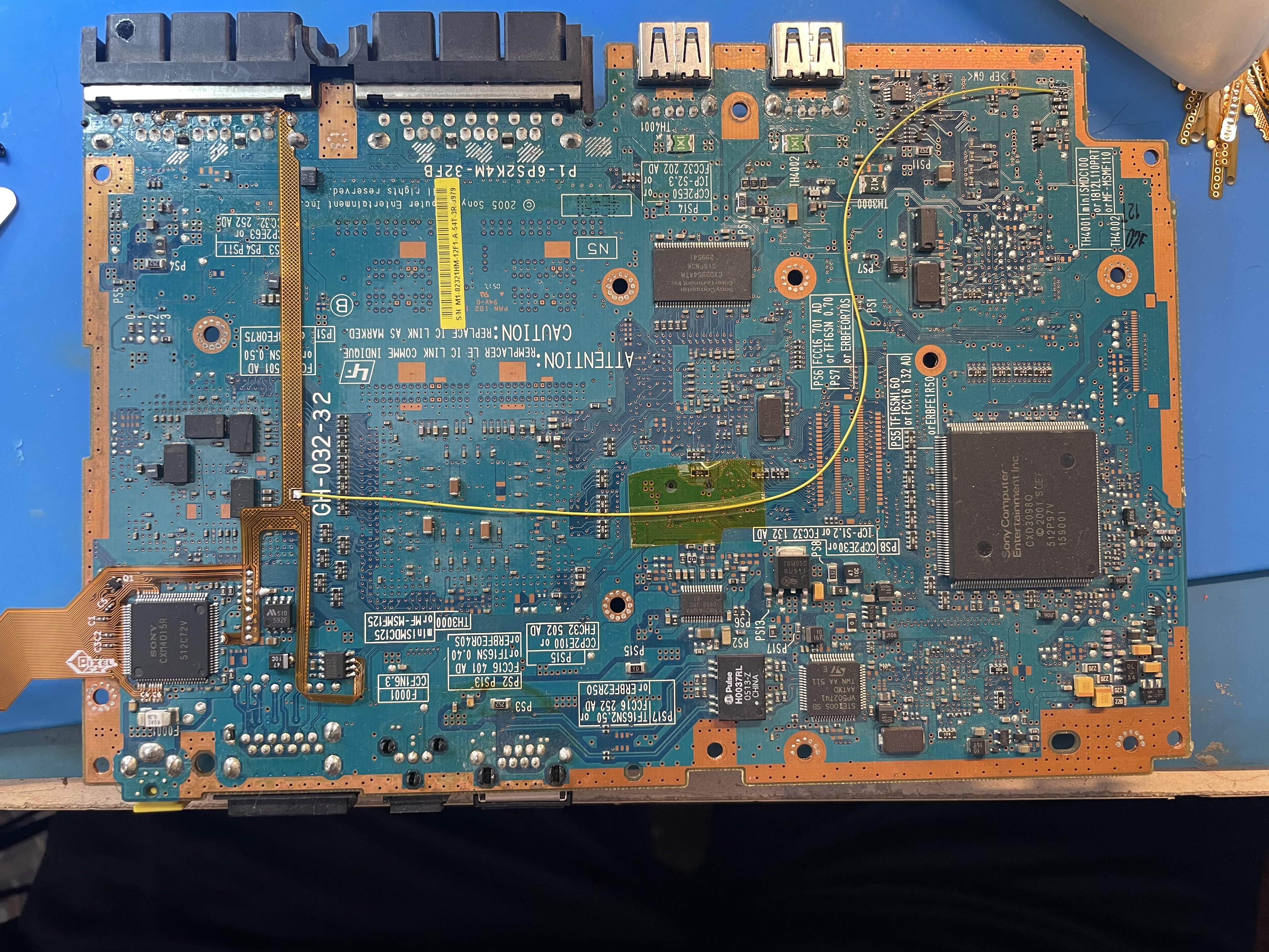
GH-032-32
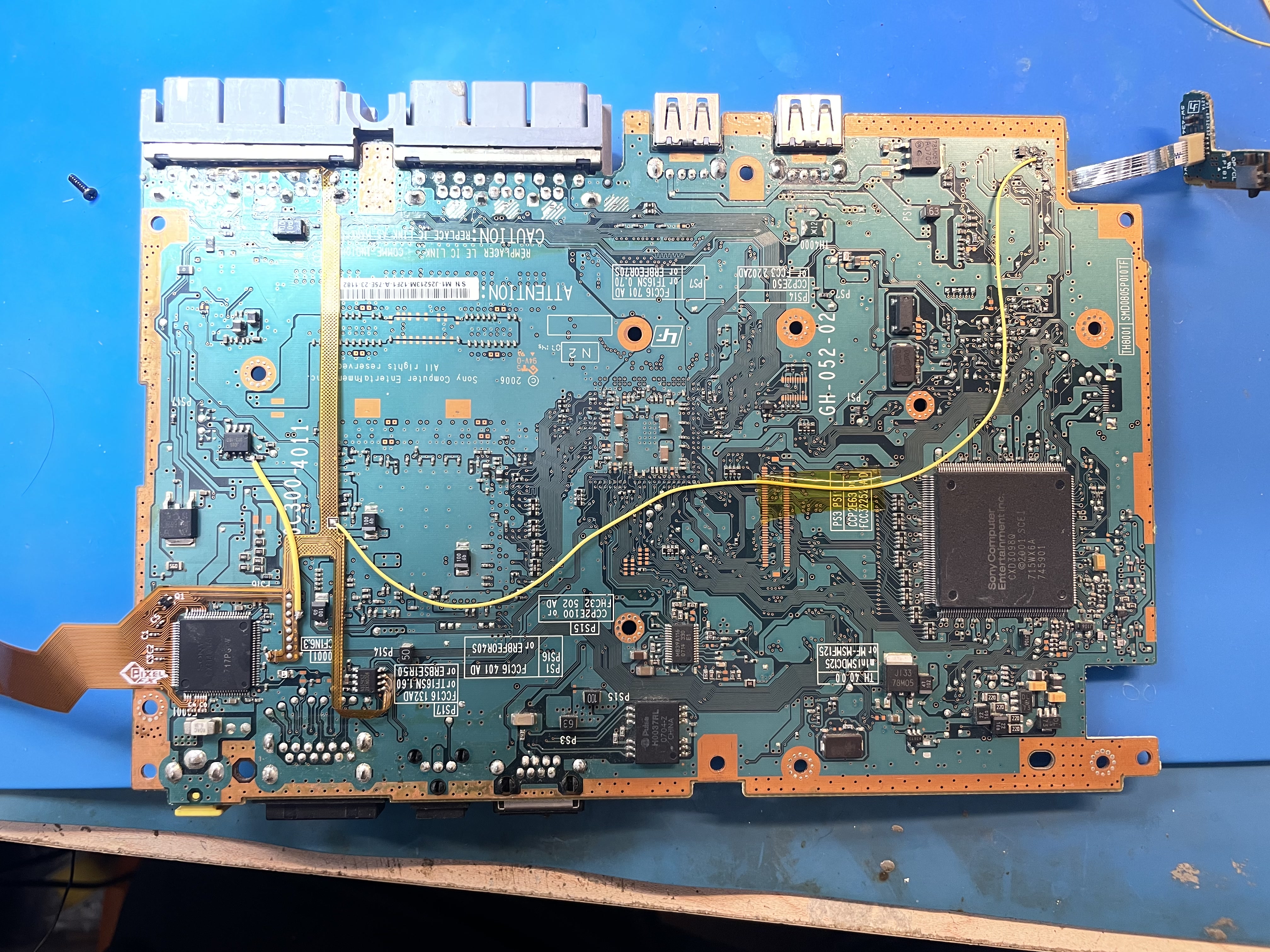
GH-052-02
Cut the bottom shield as shown

Proceed to the next step.
Rotated Bottom Side
Click to expand/collapse
This is my least favorite install as the intermediate flex has a really funky bend. I have only seen this one variant of the rotated bottom side. If your mobo power (3.3v and 5v are not the same) please send me a message.
- Remove the components in yellow.
- Red is 3.3v hookup (Pin 8 592F)
- Blue is 5v hookup (Pin 13 of CMX40xx) (Can also be found on Pin7 on the audio IC)
Isolate any pads that might interfere with kapton tape (pads that are extermely close to the CMX40xx)
Install the intermediate flex on to the controller flex
It is highly recommend you use lead free solder. The solder used in the PS2 has tin which can create micro cracks if leaded soldered is used and not mixed well. If you prefer to use leaded solder you need to wash the pins (mix) or remove the lead free solder all together. After installing many kits I personally prefer to just use lead free.
Install the main flex and hookup the intermediate flex: PAY ATTENTION TO THE 5V and 3.3V HOOKUPS
If you plan to wire 5v to pin 13 cut off the support pad on the intermediate flex. If you plan to wire the 5v to pin7 of the audio IC, do not cut the support pad. The installation below uses pin13 for 5v. This is a harder install but cleaner.
- Solder the 3.3v to the flex.
- Solder the reset wire
- Route the main flex as shown. Be gentle, as you might need to fix some bad connections etc.
Cut the bottom shield as shown
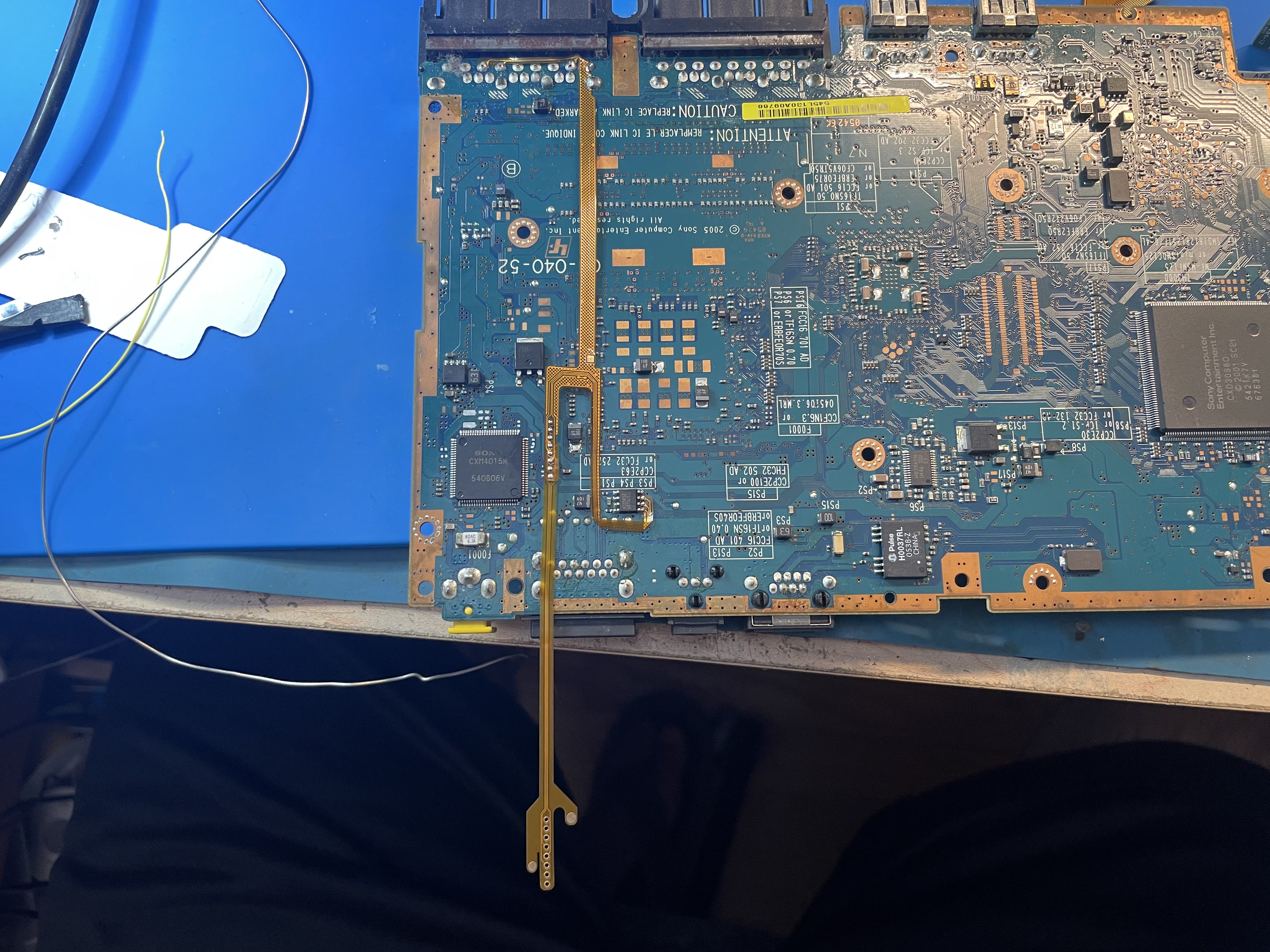
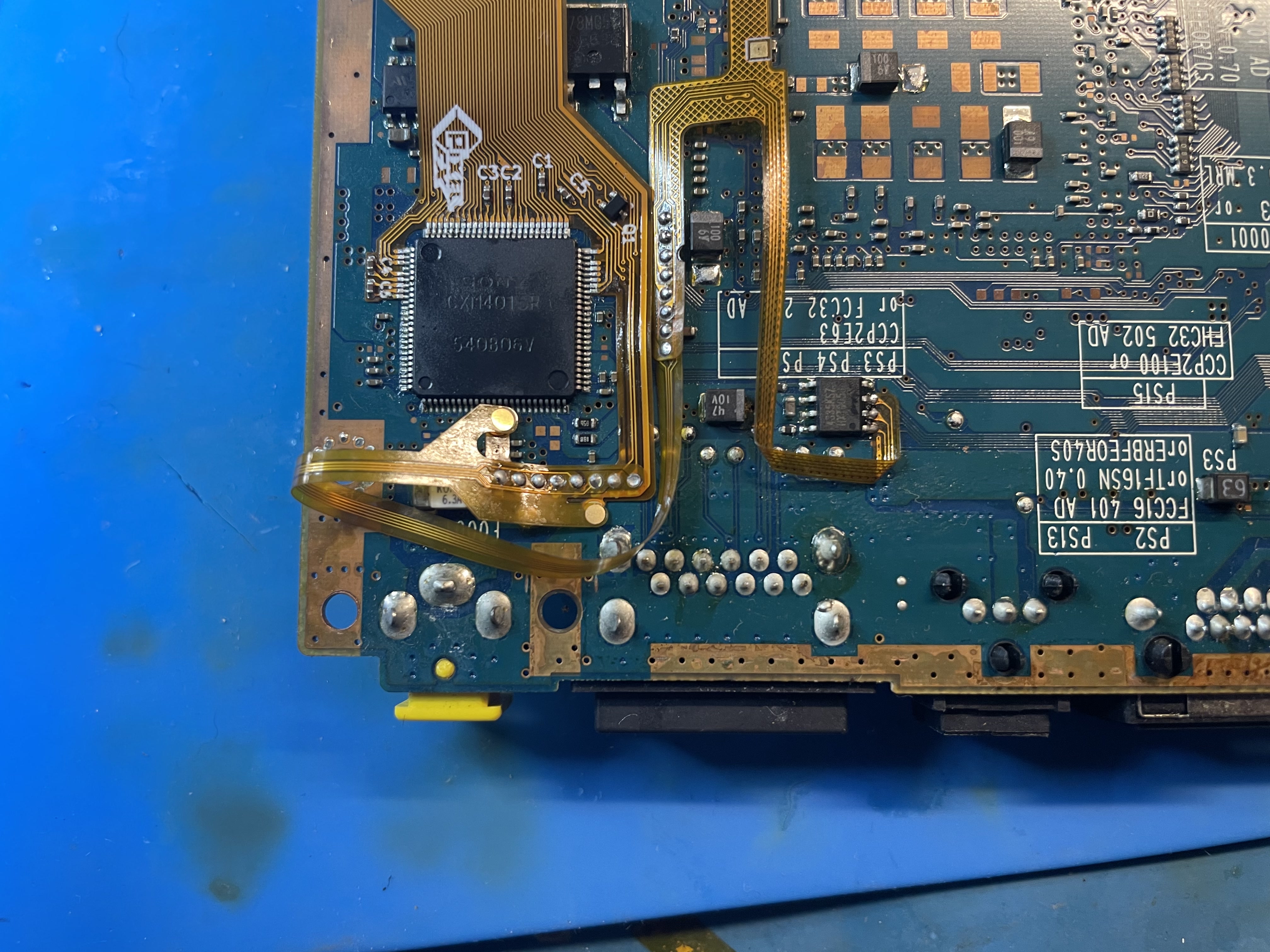
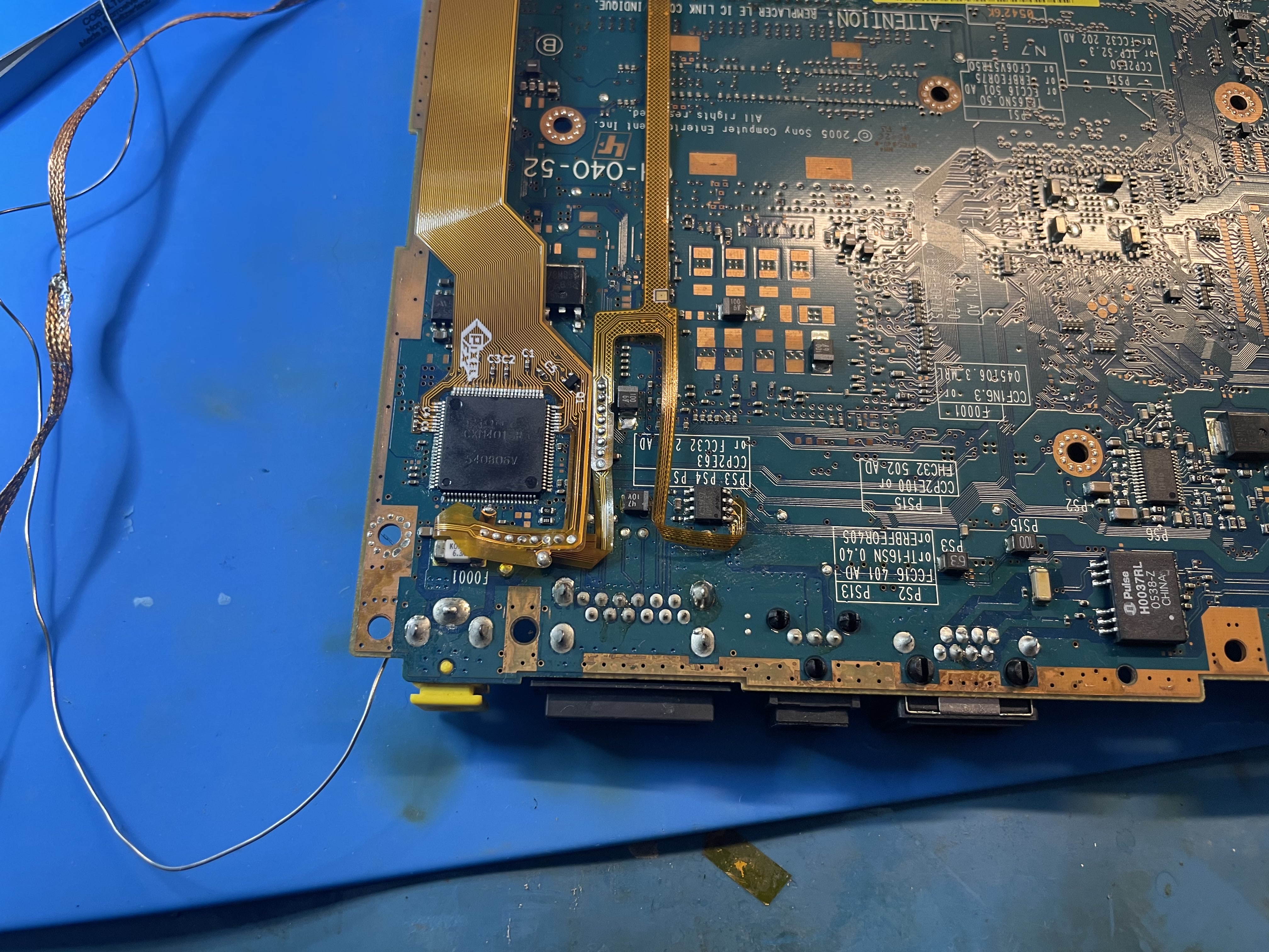
Top Side
Click to expand/collapse
This install isn't bad just follow my bends closely of the flex cable. I have only seen this one variants of the top side. If your mainboard power (3.3v and 5v are not the same) please send me a message.
- Remove the components in yellow.
- Red is 3.3v hookup
- Blue is 5v hookup. 5v is still located on pin 13 of the CMX40xx but it seems almost impossible to solder to the pin leg with the flex casteleation.
Solder the intermediate flex to the controller flex.
Solder the main flex and bend the arm as shown
- Solder the intermediate flex to the main flex. Pay careful attention to how the flex bends and routes.
- Solder the 5v and 3.3v hookups.
Route the flex as shown, be careful and do not bend too tight as you might need to open back up to fix any connection issues.
Cut the highlighted areas off of the top shield:
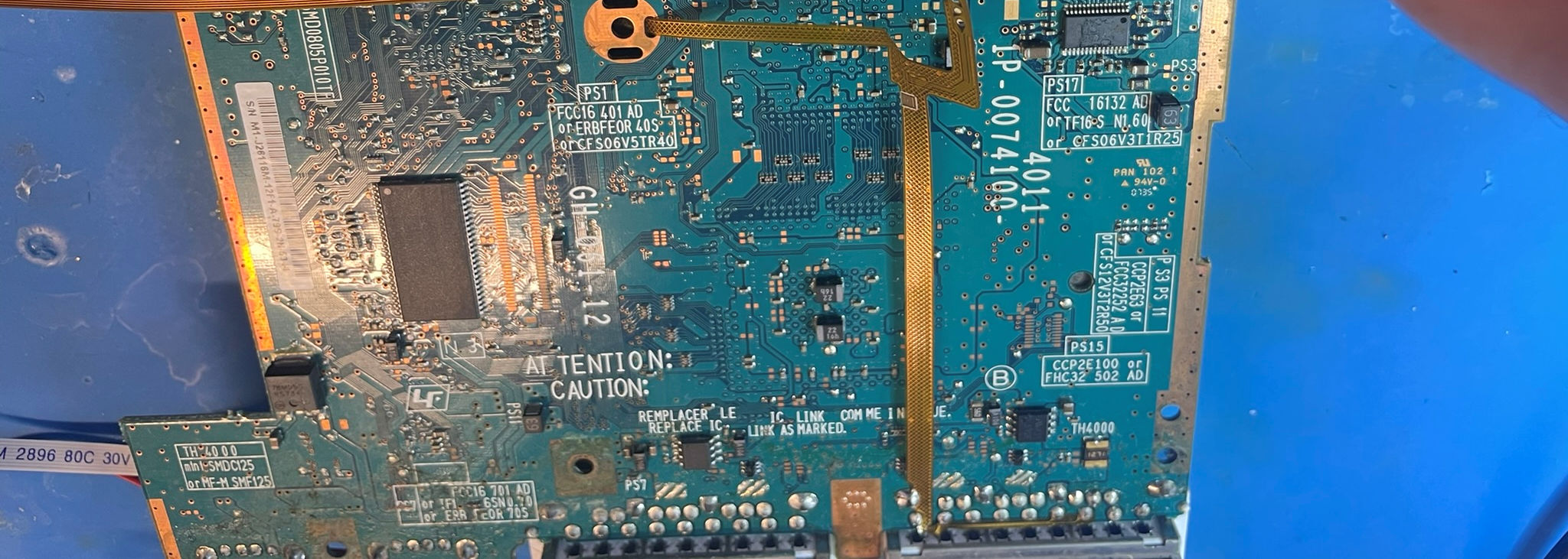
79K
Click to expand/collapse
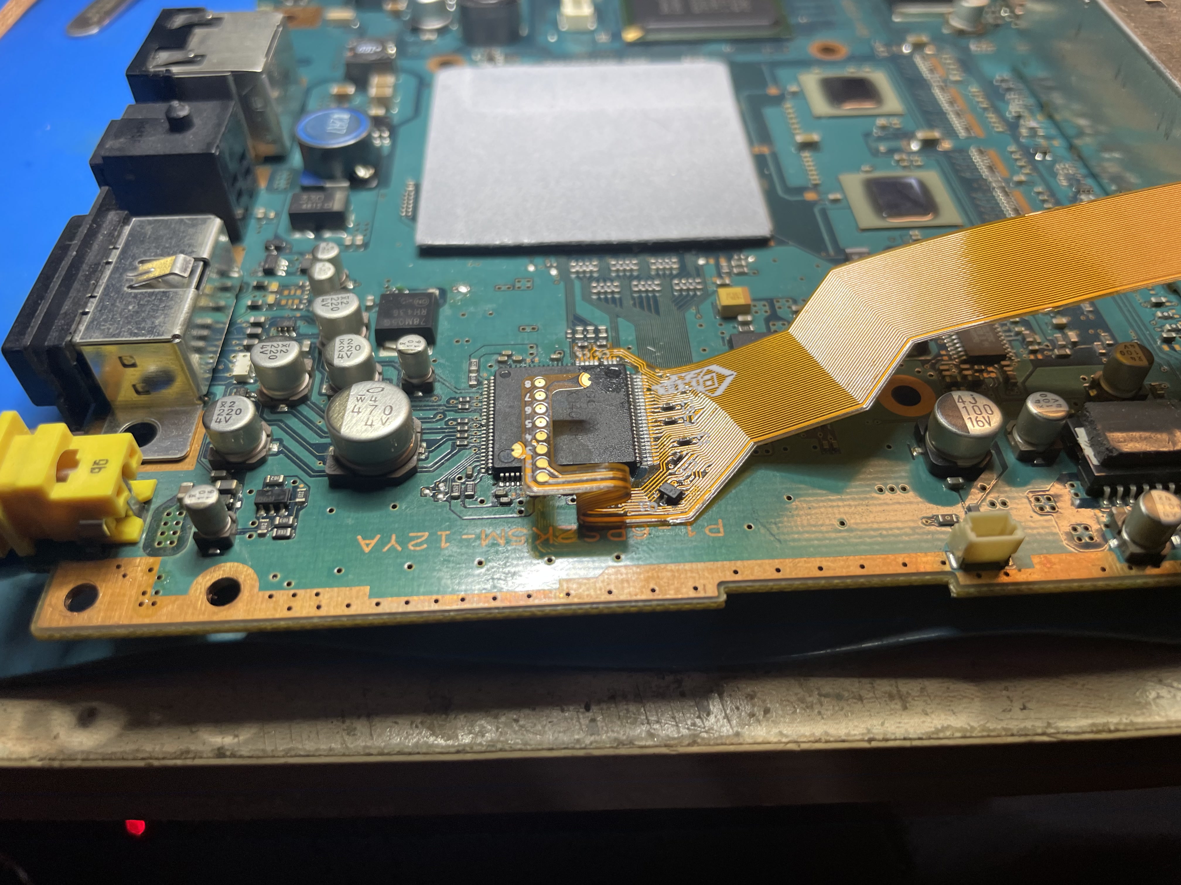
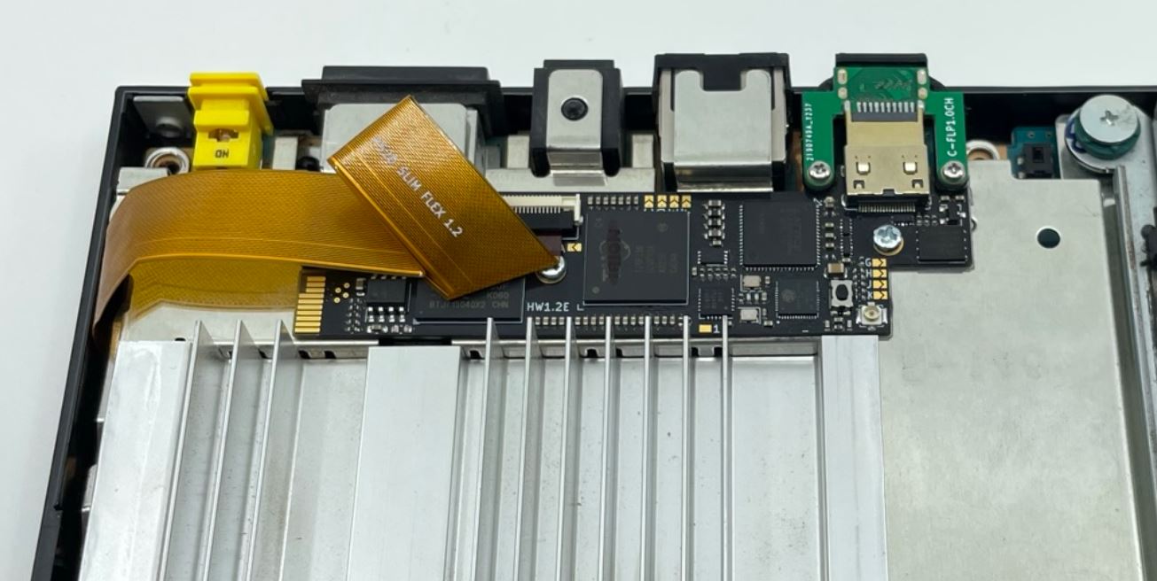
Install the main flex as shown.
Install the intermediate jumper flex to the controller flex.
Install a small jumper wire to hookup 3.3V and secure all flex cables.
Install the Reset wire
Bend the main Flex cable as shown. Align the GEM and secure it into the shield. Use the M2 screw and nuts.
Step 5 - Testing
Click to expand/collapse
Its possible to test the console with it partially dissaembled. Be extremely careful.
Before testing its highly recommend you test each pin to verify no pins are bridged. Use the pinouts page for support.
Partial shorts (100ohm) are expected between ground and the power rails from bleed off resistors.
Before attaching the retro gem confirm the analog/composite video still work correctly. If you have any problems with composite this will signify you have bridged or discconneted pins.
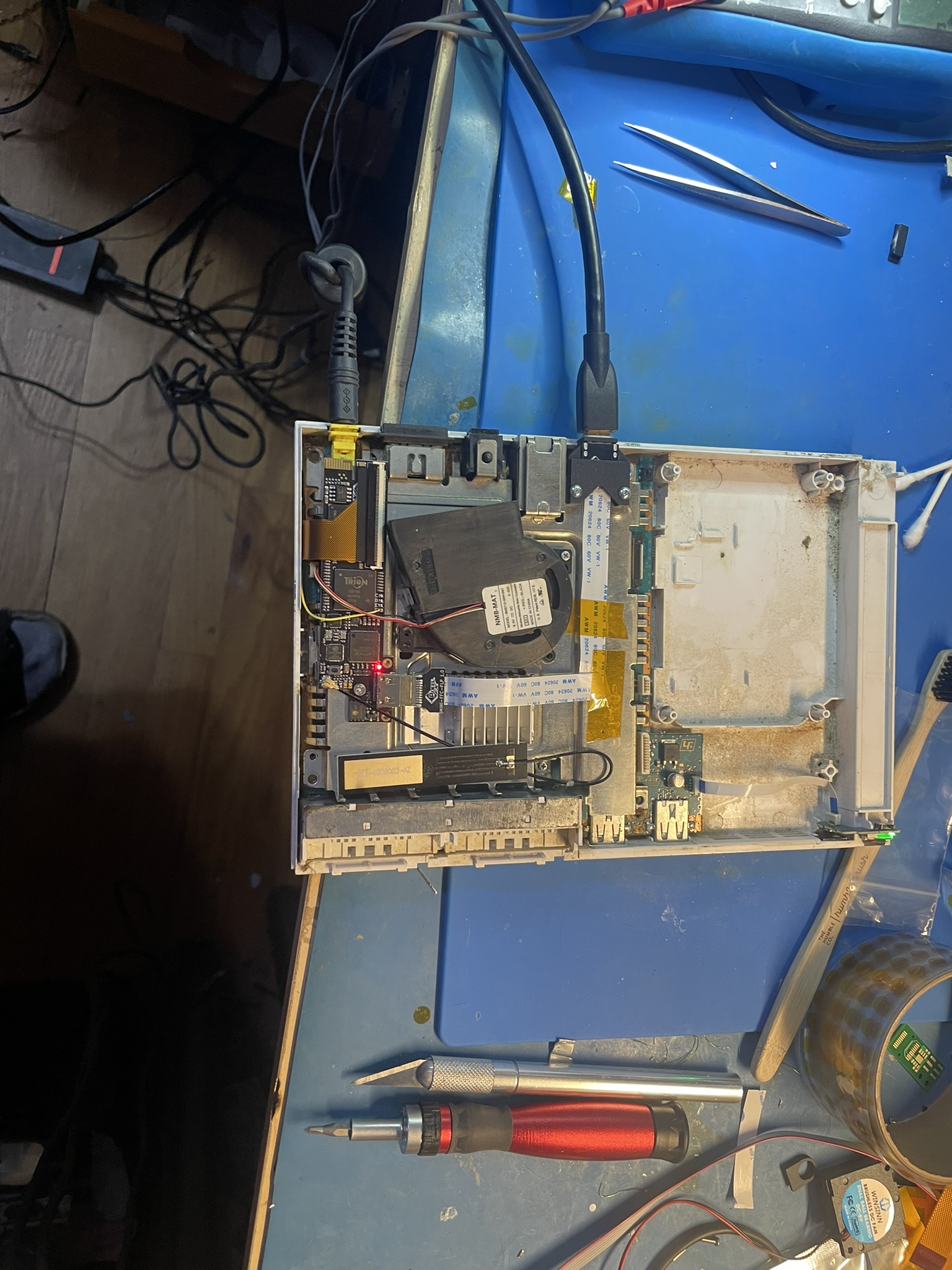
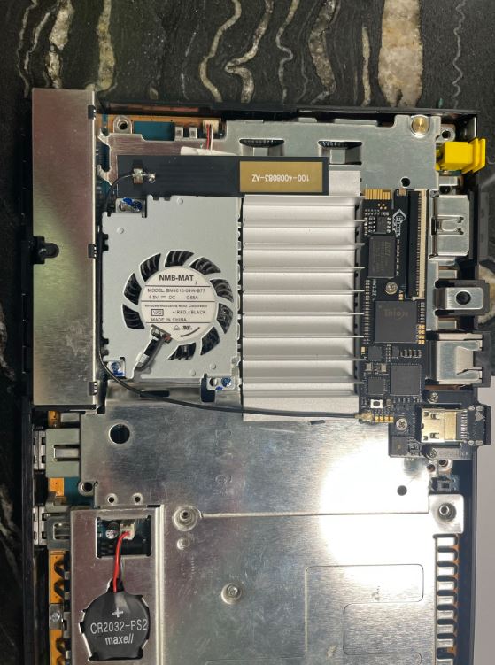
Step 6 - Finishing up
Click to expand/collapse
After confirming everything is working correctly, go ahead and install the antenna. I like this route:
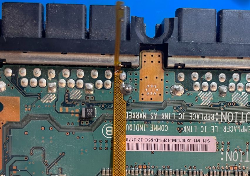
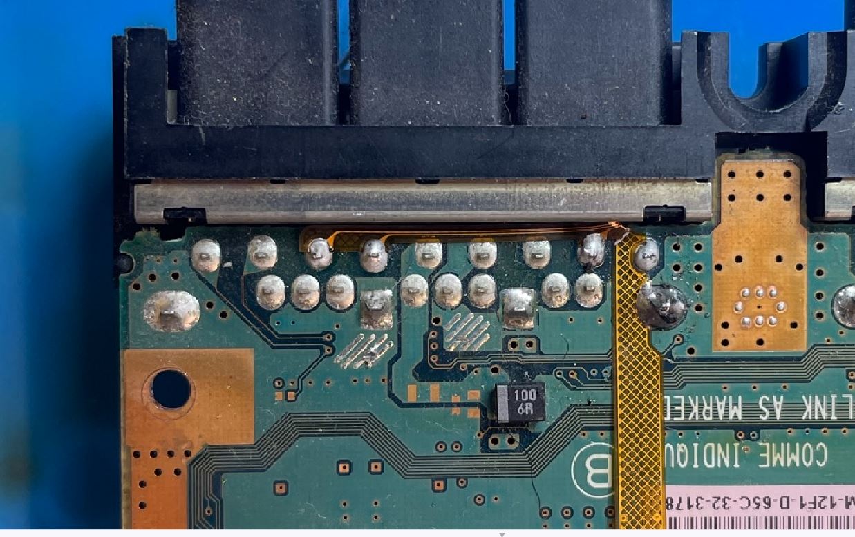
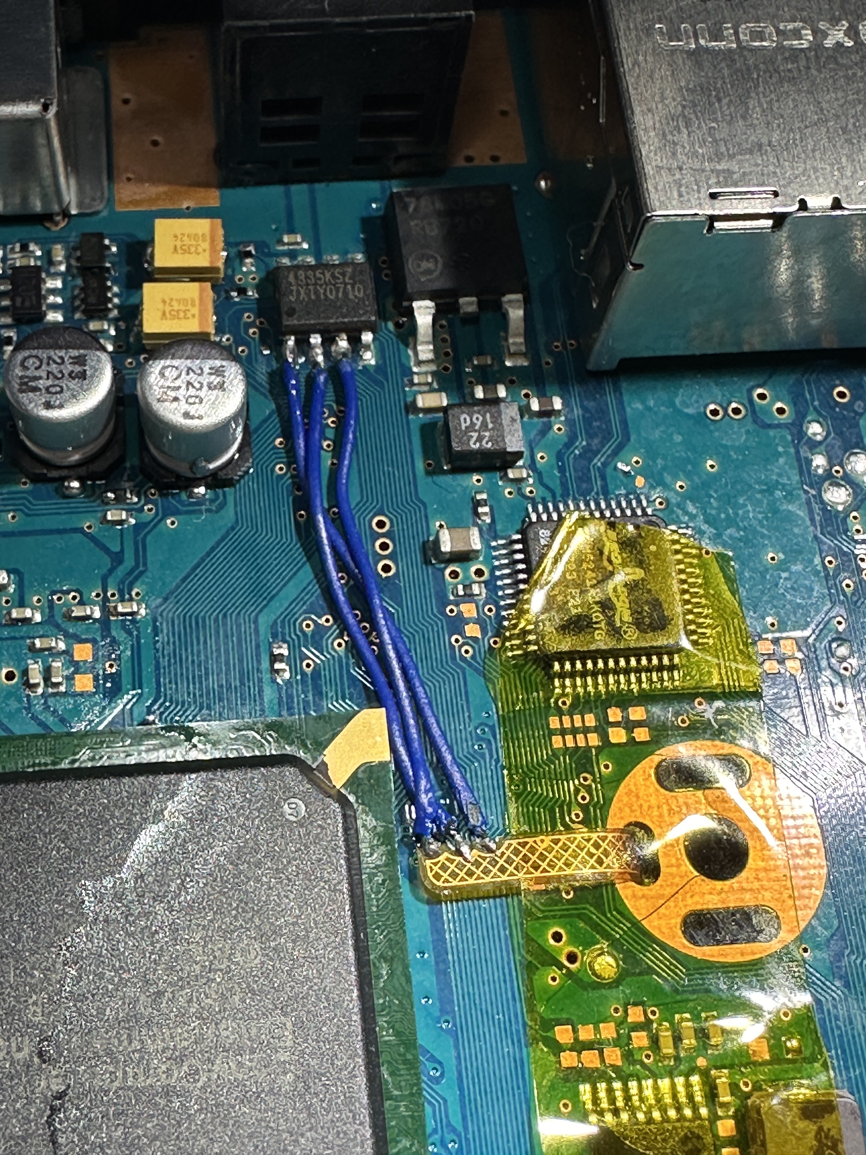
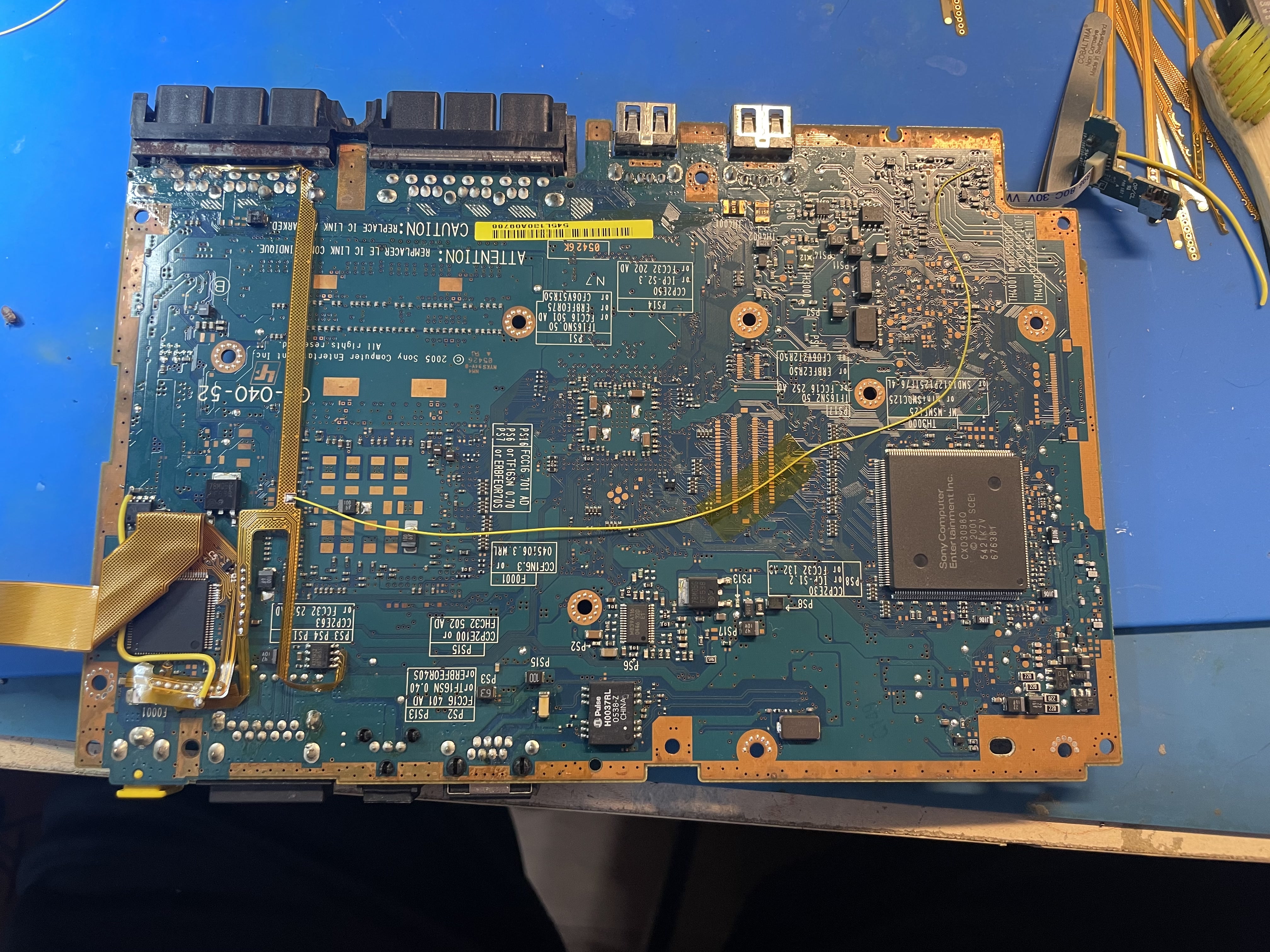
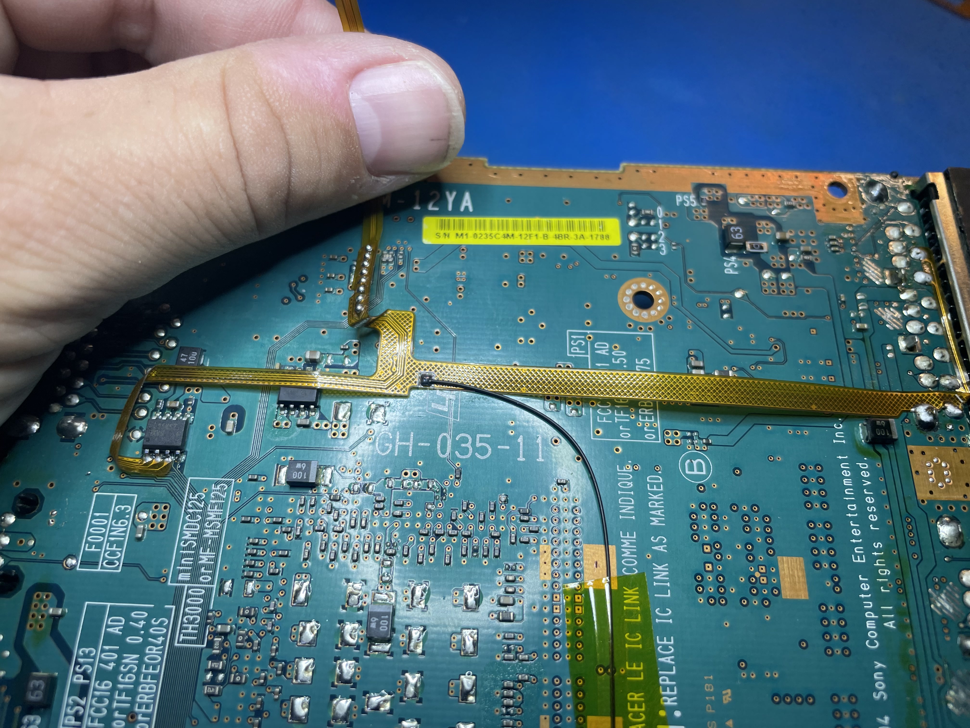
Wire the other end of the SPDIF wire to the GEM board only to PAD 1 of Jumper F as shown. Make sure the wire is not pinched by the metal shield when routing.
If you have a top side dac route your flex cable as shown:
If you have a bottom side dac route your flex cable as shown:
That is the installation, thanks for your support! Any problems or concerns let me know.