Retro GEM PS2 Fat Installation Instructions
Disclaimer: This kit is for advanced installers only. Install at your own risk. We cannot be held responsible for damage to your console and/or kit. Each kit is individually tested and confirmed working before being shipped.
Before you begin:
Please review the installation video. Always reference these install docs and use the video as an aid for techniques on how to preform the required steps.
https://youtu.be/yOr3tjqLXrw
Pre 39K (GH-015 and earlier) motherboards are now supported These require an additional flex that can be purchased here: https://www.pixelfx.co/product-page/retro-gem-kit-replacement-parts This is a hard flex to install and should only be preformed by an expeierecnced technician.
Some PS2 fat motherboards have a large crystal (18.432MHZ) in the way. The flex can still be installed with this crystal. However a low profile cyrstal with identical freqency can be used. IE: ECS-184-18-23A-EN-TR/2213742
If you plan to use wires for your controller installation you must update the firmware on the retro GEM after installation. The controller might not work initially, and this is expected with wires. You can update your firmware to the latest firmware using a CEC (Your TV remote), or the rescue system.
Kit includes:
- PS2 Fat Main Flex
- PS2 Fat Controller Flex
- PS2 HDMI Mount
- Plastic Mount
- Mini Flip HDMI Adapter
- M3 6m Screw (2x)
- M3 Nut (2x)
- M1.6 Screw (2x)
- M1.6 Nut (2x)
Items required
- Temperature Controlled Soldering Iron
- Lead Free Solder (Leaded solder is ok, but must solderwash)
- Non Corrosive, No Clean Flux (Amtech 559 / Kester 959T)
- 99% Isopropyl Alcohol
- Multi Meter
- Solder Braid / Desoldering Tools
- Small Phillips screw drivers
- Kapton Tape
Step 0 - Understanding the GEM Kit and Setting the GEM Jumpers
Use the online config tool to setup the jumpers for your retro gem. Just bridge the jumpers shown in the tool.
https://docs.pixelfx.co/fxdigital-config.html?c=ps2
This guide will not go over the tear down or small nuieces of the installation. Please watch the installation videos for this information.
The typical install procedure is:
- Test the console
- Teardown the console
- PS2 Main board prep
- PS2 Main Flex installation
- PS2 Controller Flex Installation
- Reset Hookup
- Testing
- Reassembly
Step 1 - PS2 Fat Board Prep
Click to expand/collapse
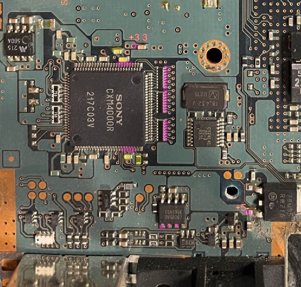
The 18.432MHZ crystal can be replaced if chosen at this time. There is no polarity on this part.
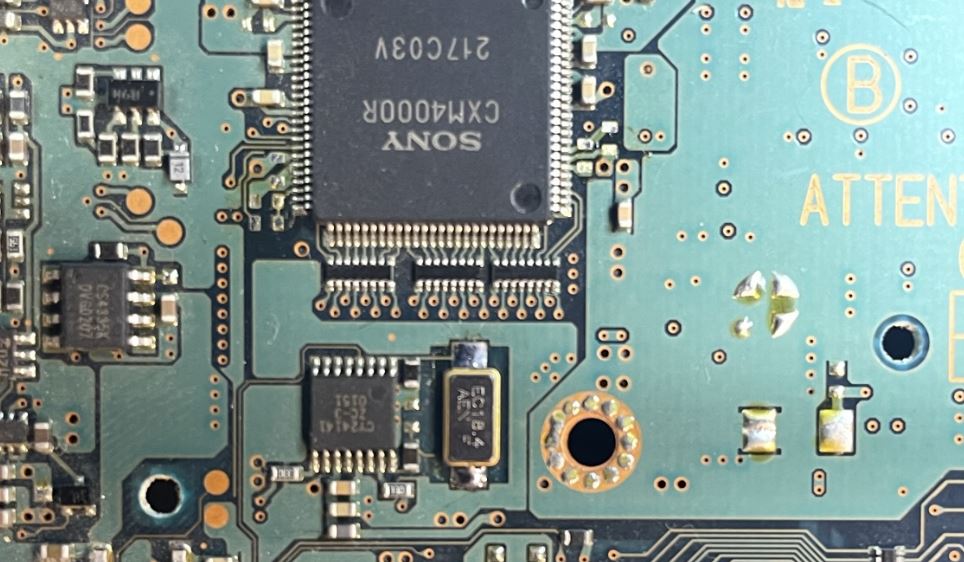
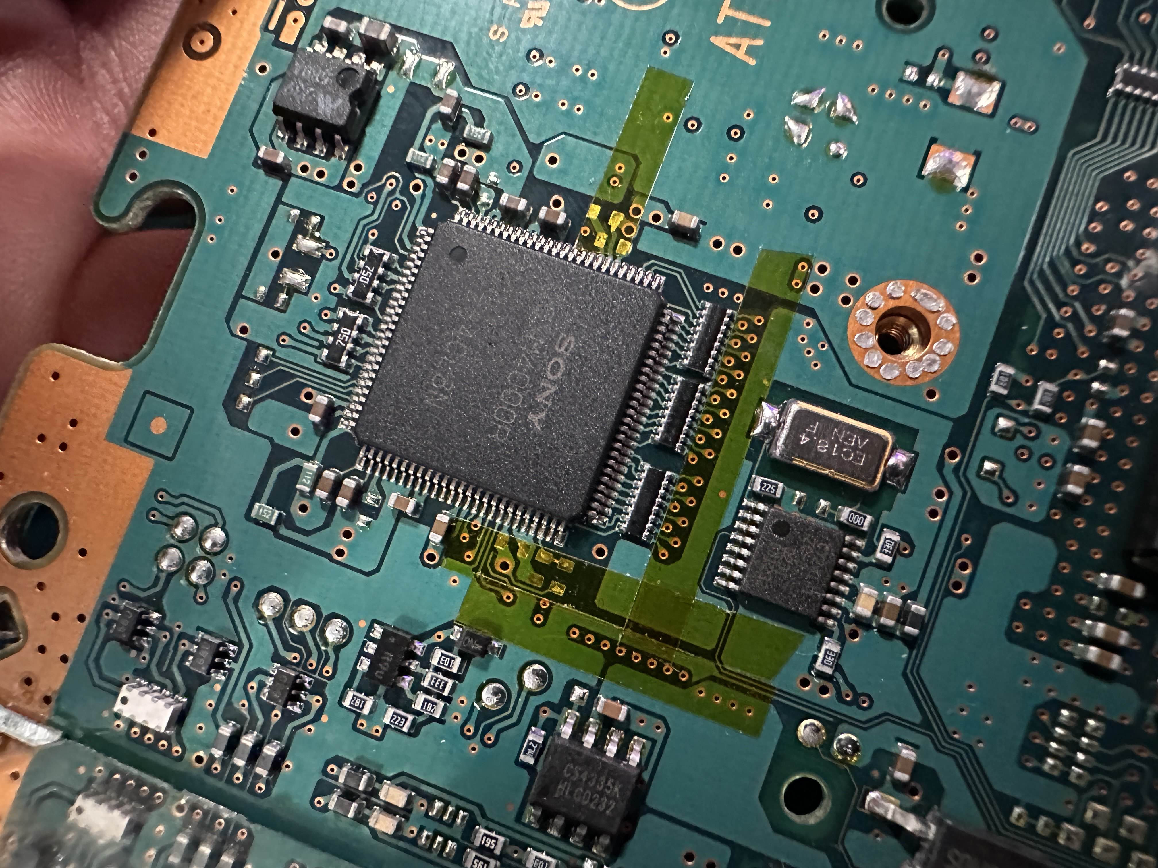
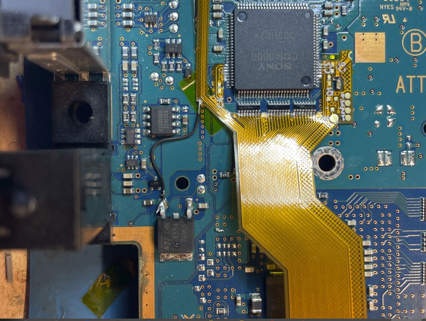
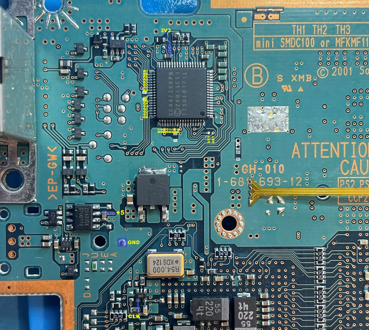
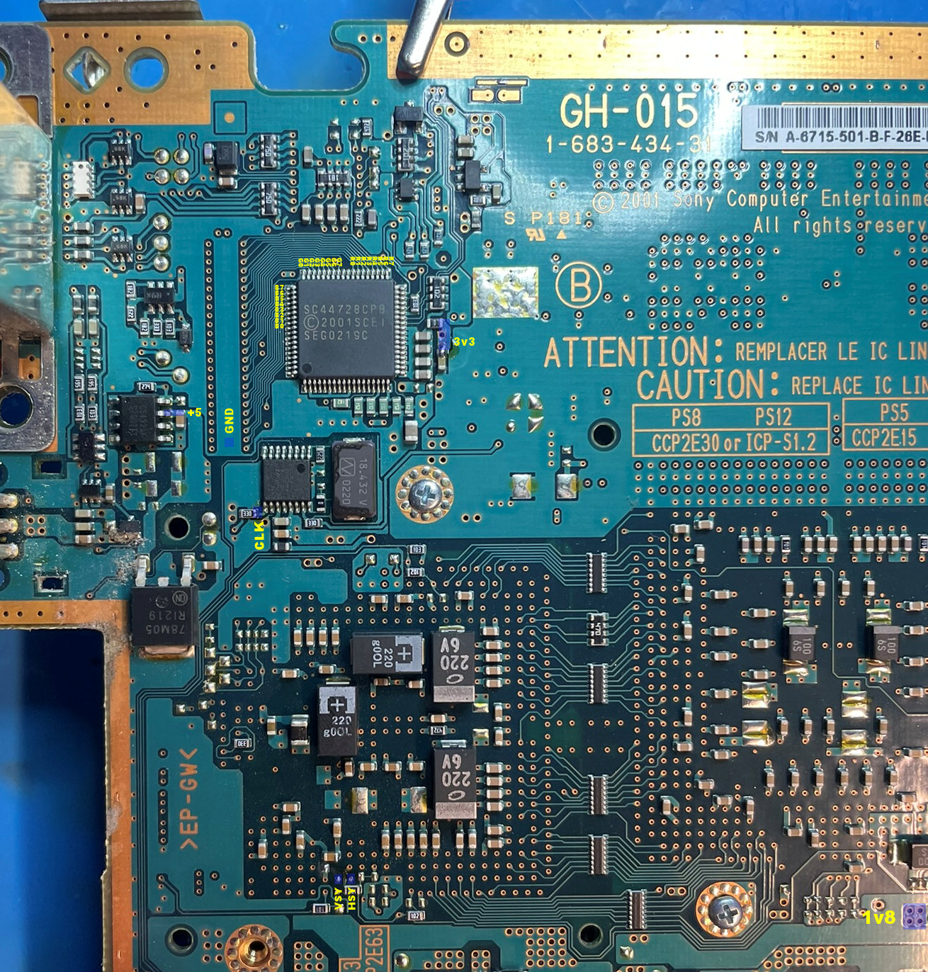
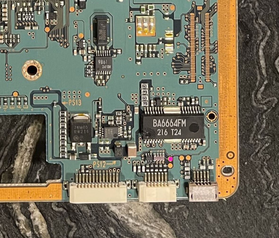
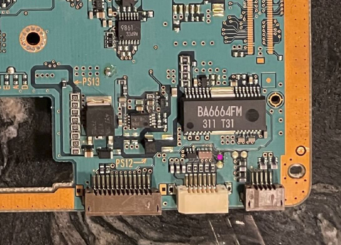
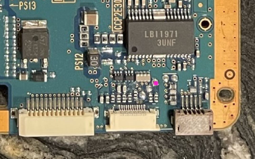
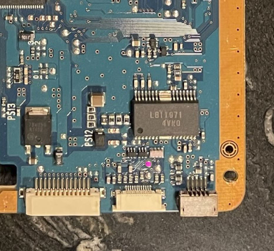
Components highlighted in yellow need to be removed.
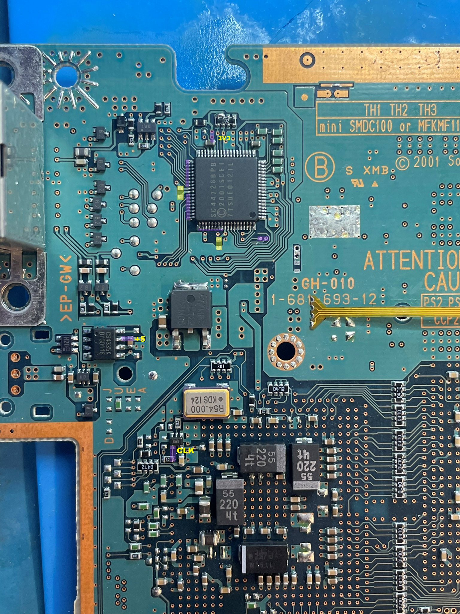
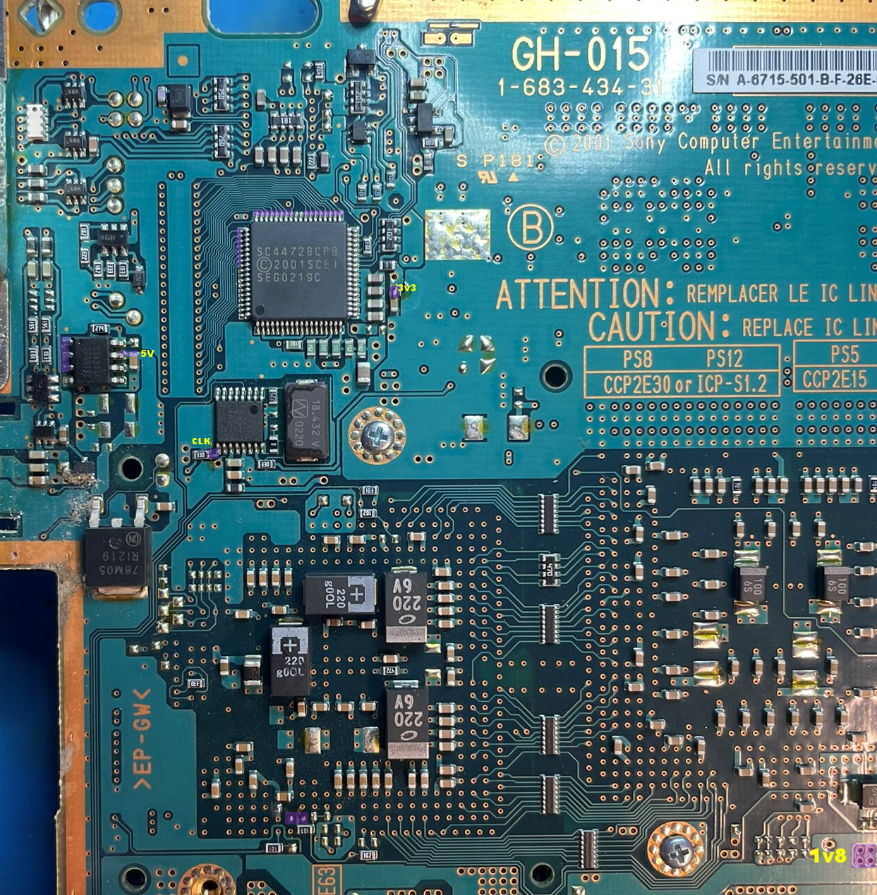
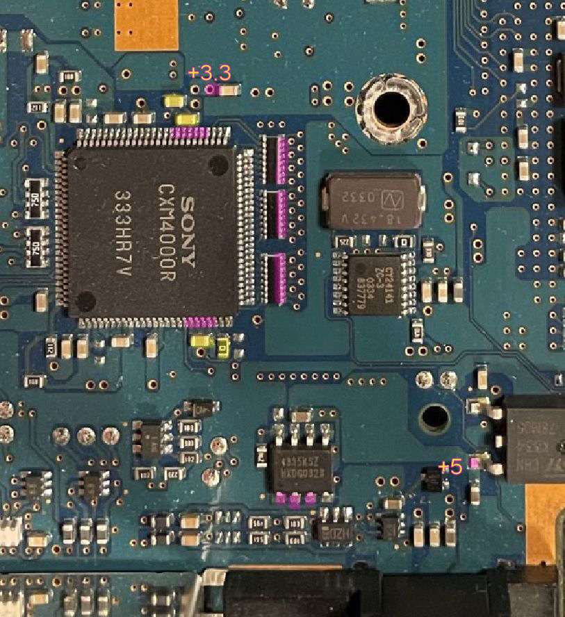
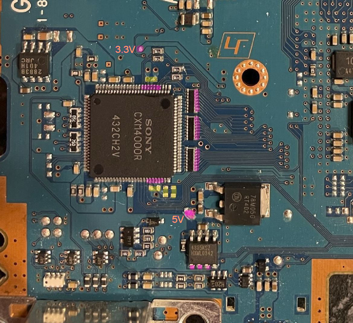
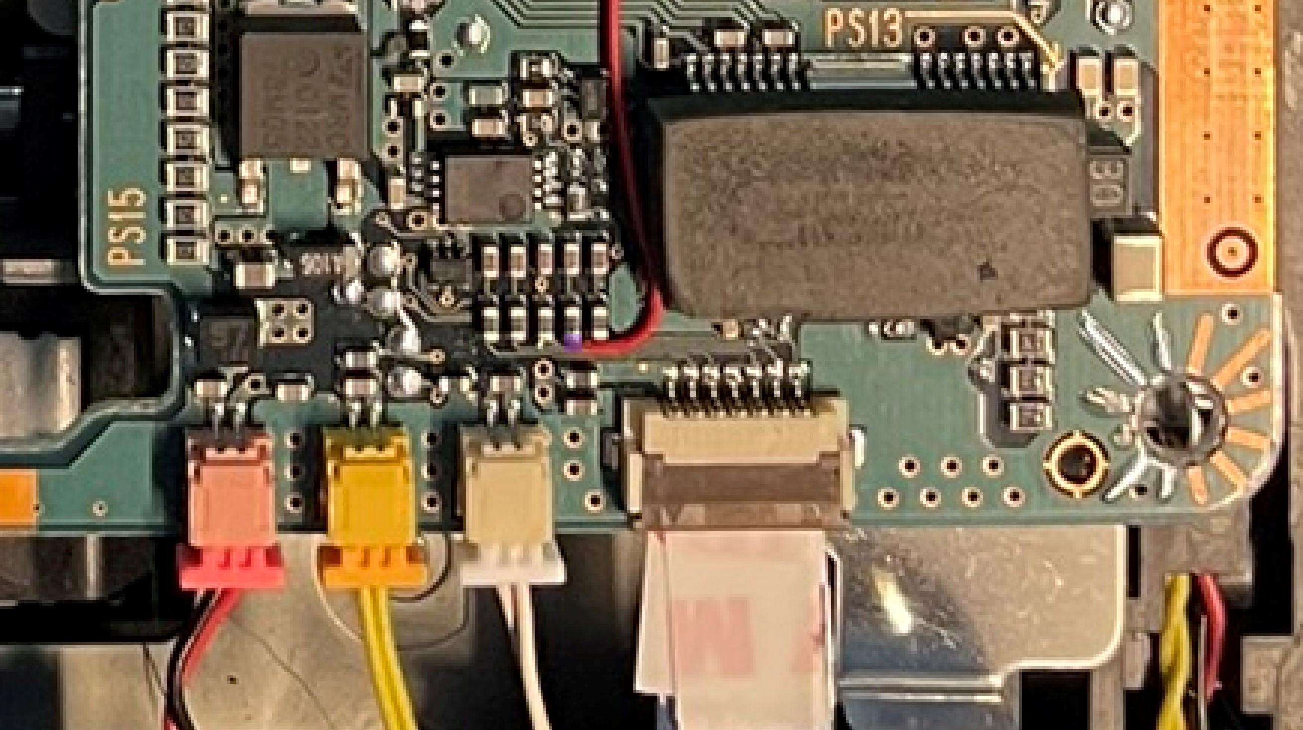
The areas marked in purple are where the flex will be soldered, Pay attention to the 5v and 3.3v areas.
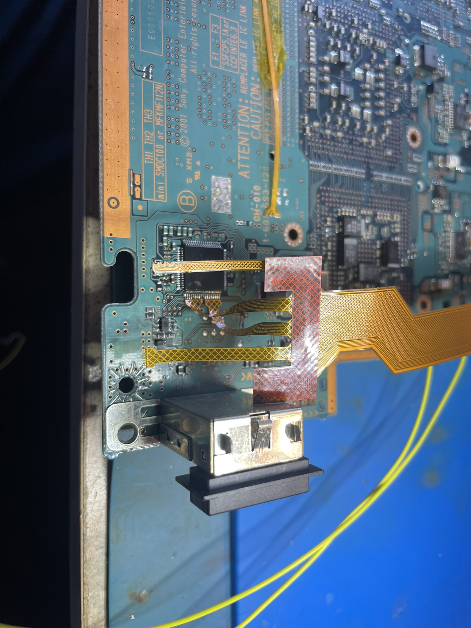
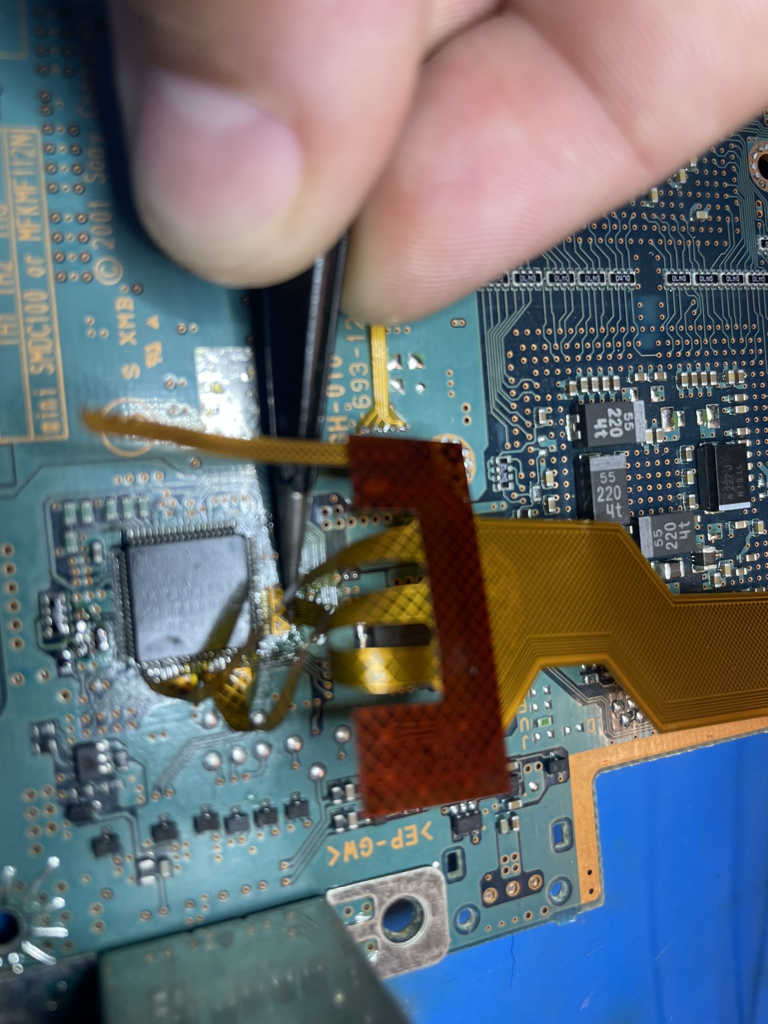
The toslink port also needs to be desoldered and removed.
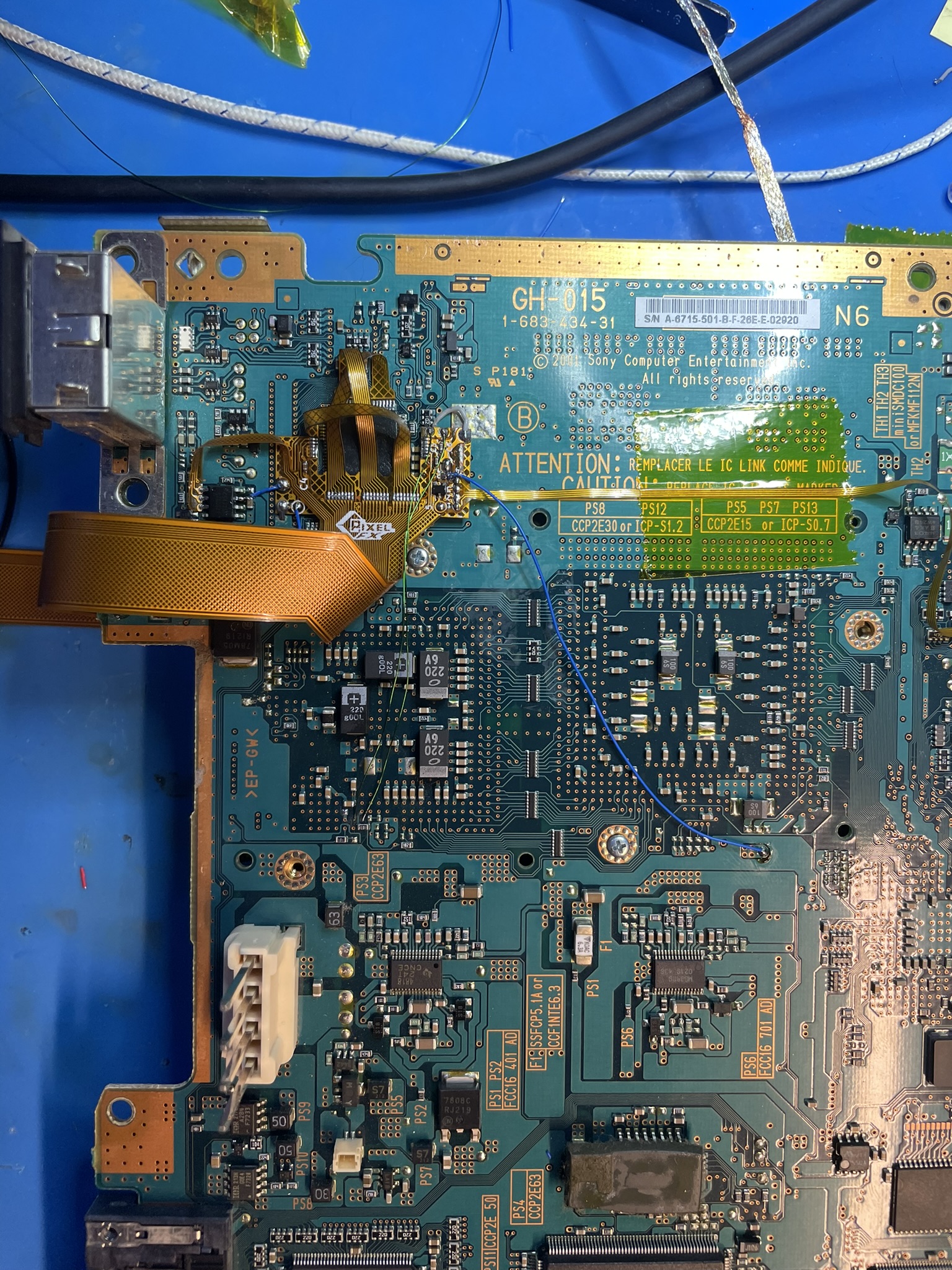
GH-010
GH-015
GH-019
GH-022
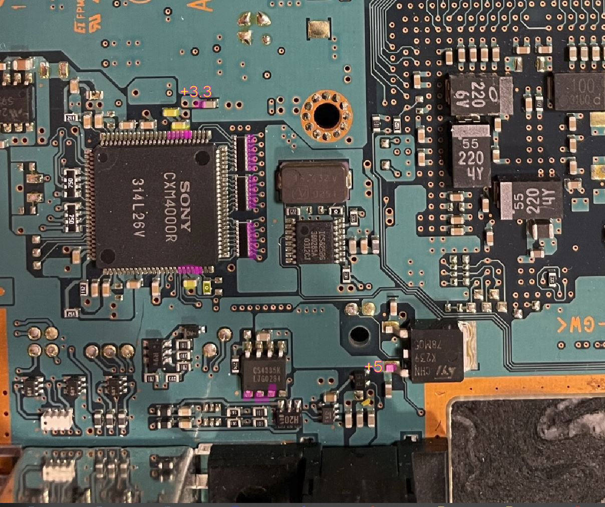
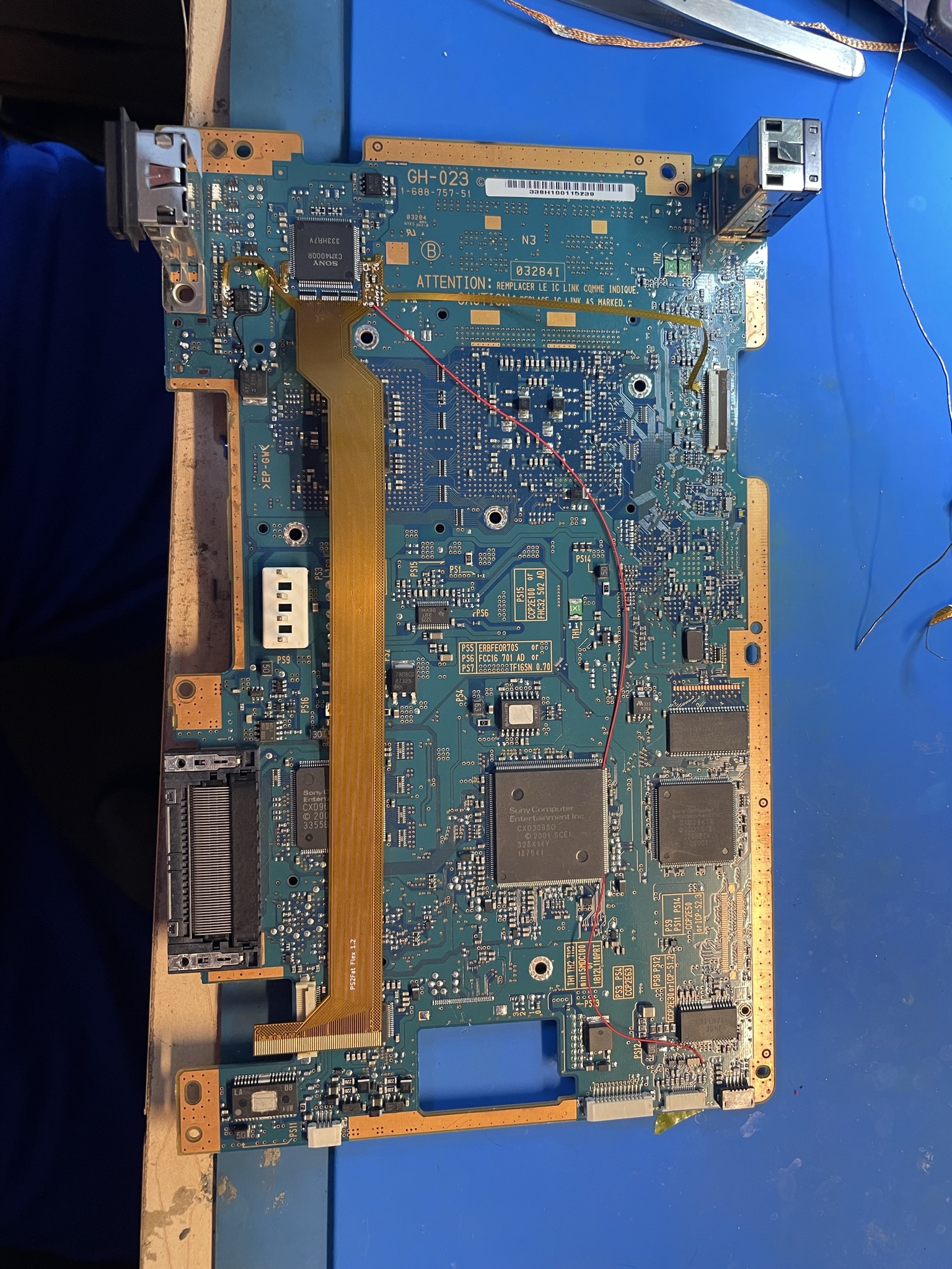
GH-023
GH-026
Step 2a - Installing the Main Flex (GH-019 and higher)
Click to expand/collapse
It is highly recommend you use lead free solder. The solder used in the PS2 has tin which can create micro cracks if leaded soldered is used and not mixed well. If you prefer to use leaded solder you need to wash the pins (mix) or remove the lead free solder all together. After installing many kits I personally prefer to just use lead free.
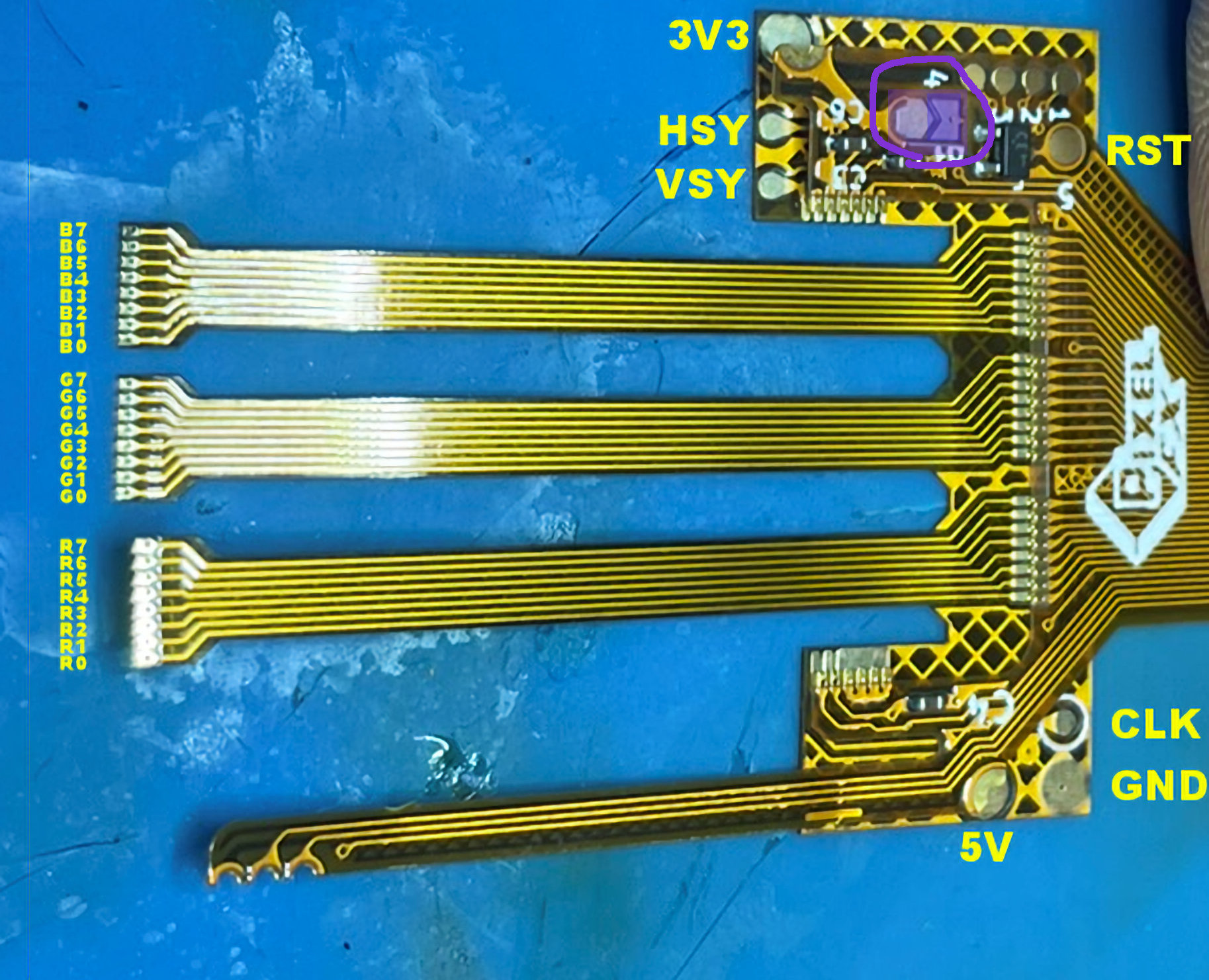
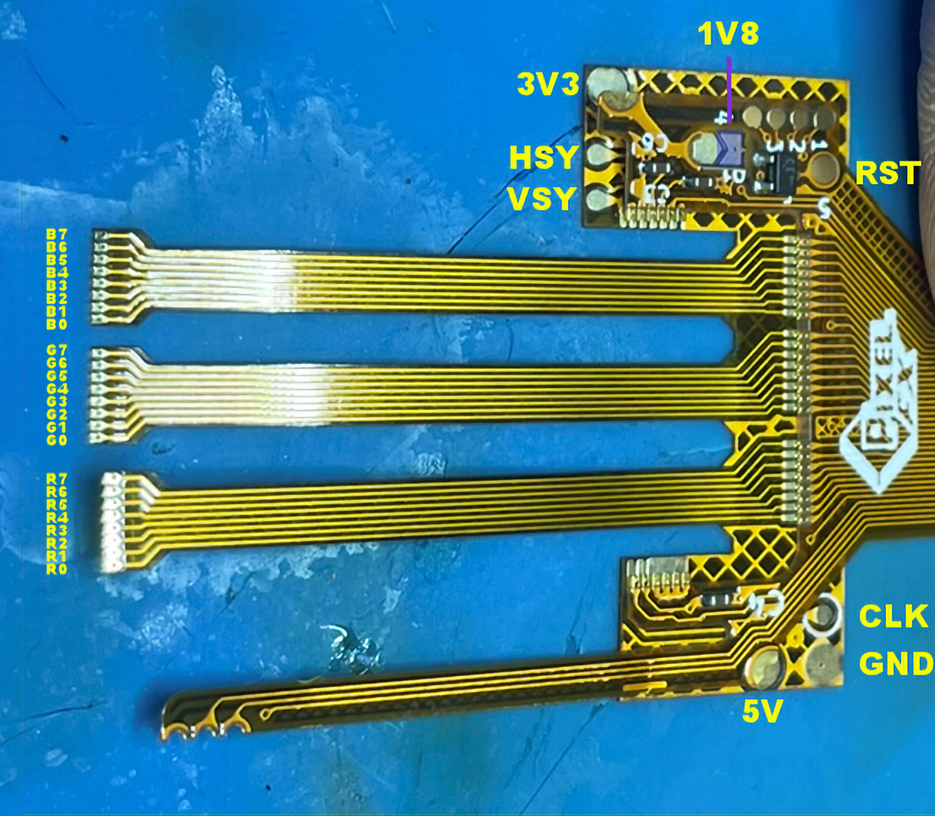
Refer to this image for the pinout:
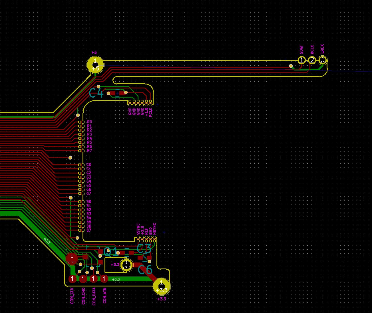
All 39K+ motherboards revisions have the same video and audio hookup points. The 3.3V and 5V can be different Please refer to these images in step 1 for hookup points.
For the rest of the installation I will be installing into a GH-023. If your motherboard is different continue following but use the motherboard 3.3V and 5V hookups in the images above.
Lets begin!
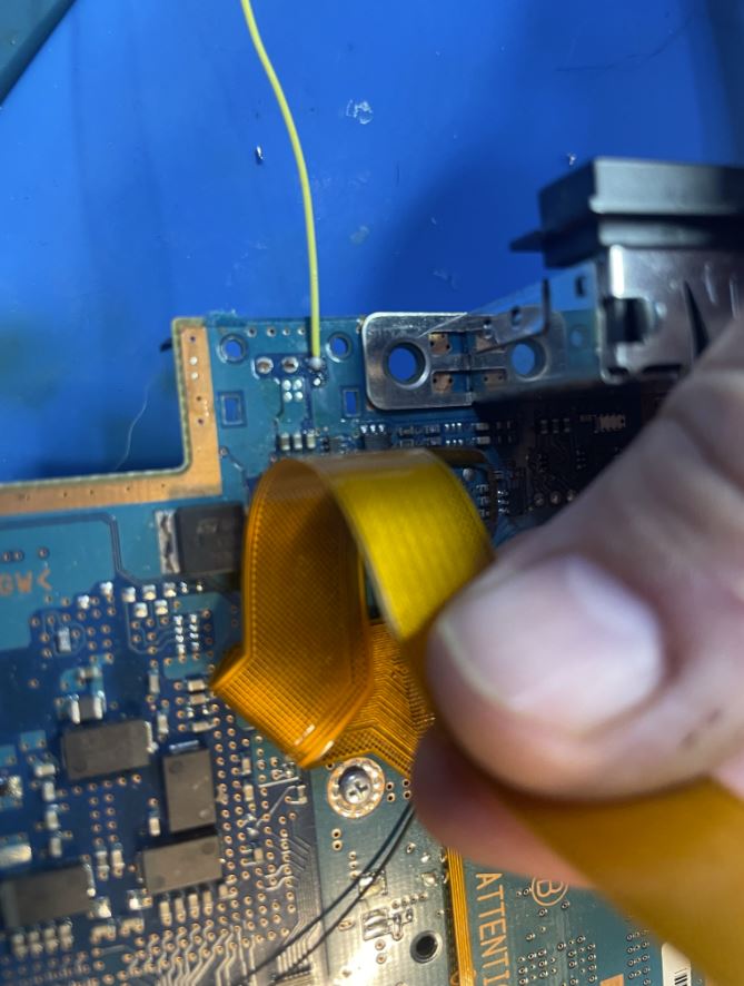
Add a small kapton tape to the following areas to make sure the flex does not short to any via.
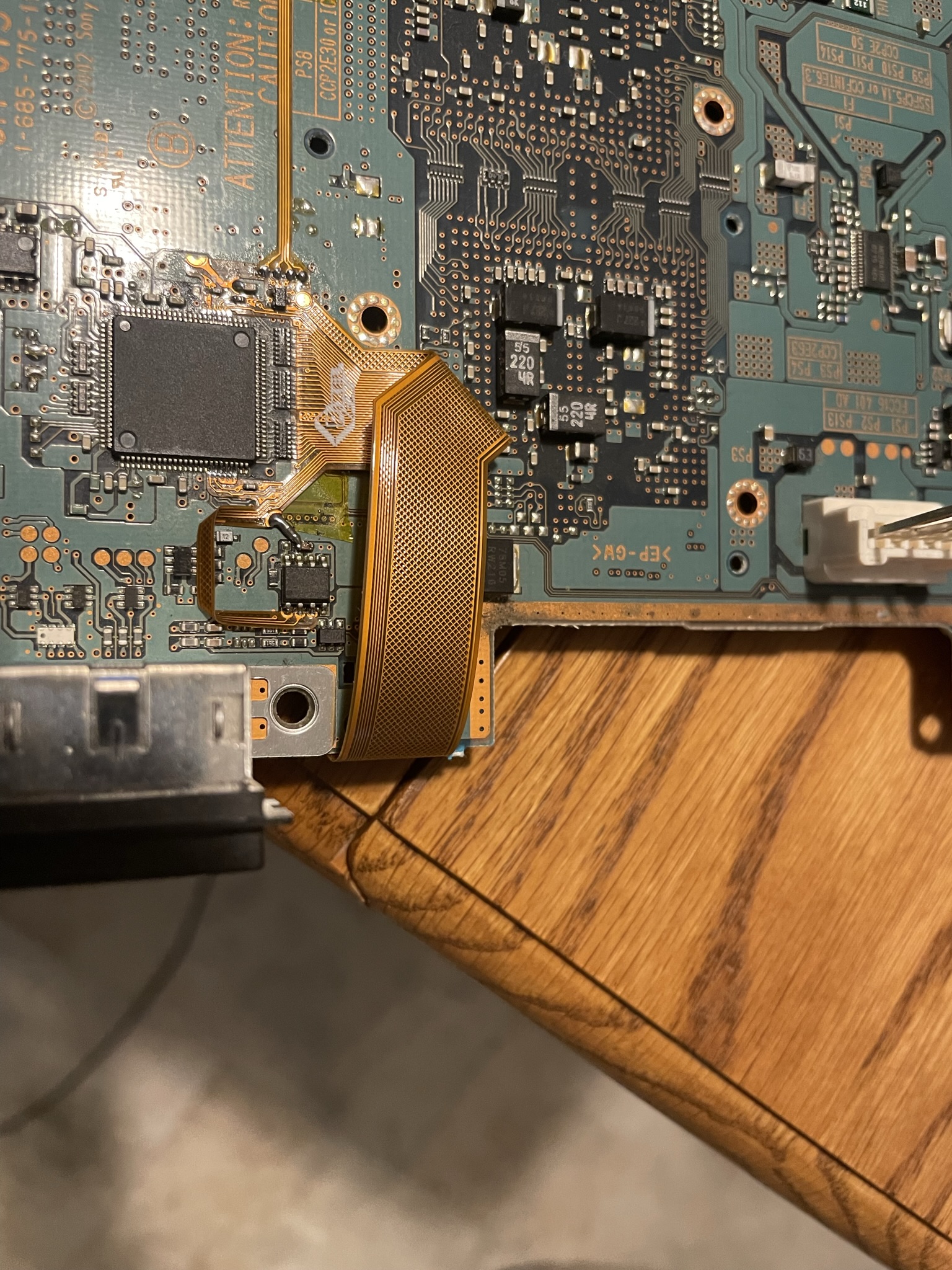
Align the main flex and solder into place, also add kapton tape in this area so the 5v is not shorted.

Solder the 5v line.
Solder the audio flex leg to the audio ic.
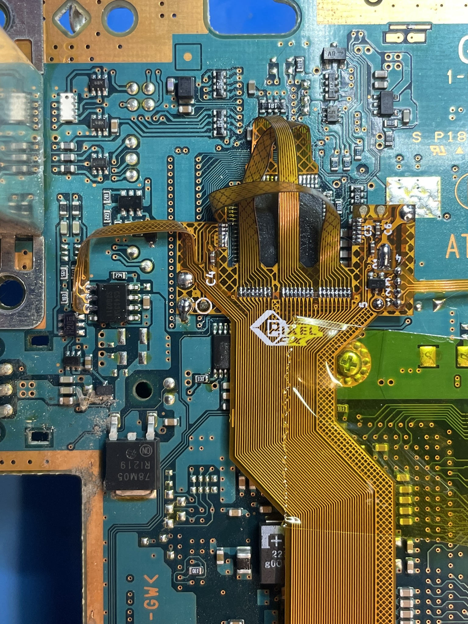
Step 2b - Installing the Main Flex (GH-015 and lower)
Click to expand/collapse
GH-010 through GH-015 motherboards (Pre 39K) require an additional flex that can be purchased here: https://www.pixelfx.co/product-page/retro-gem-kit-replacement-parts
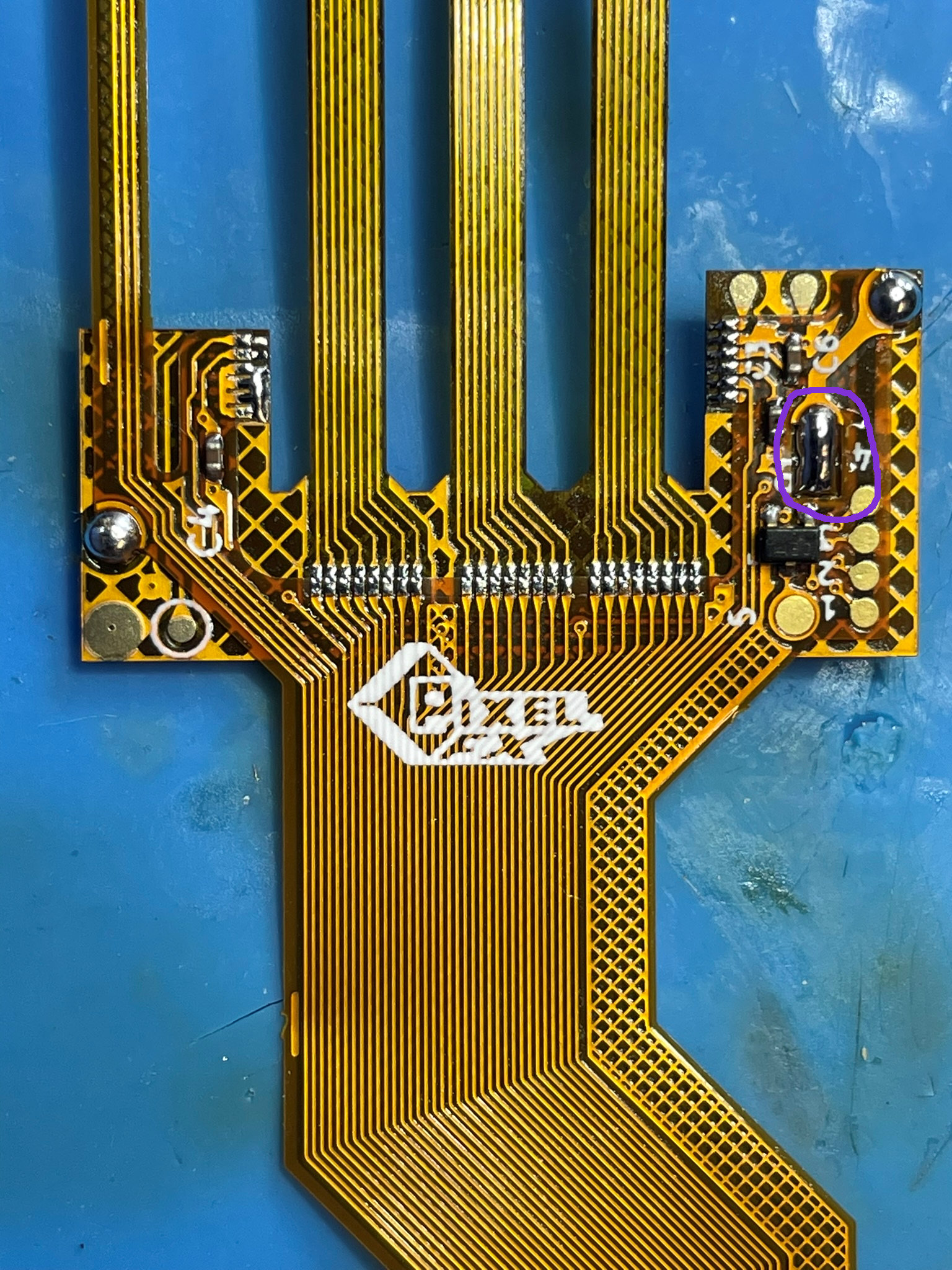
Solder the adapter flex to the main flex. Do not bridge the 3V3 Jumper (circle in purple) if you have a GH-015.
Now choose your motherboard based on the pictures and follow the pictures. You will need to solder some extra wires as compared to the other fat installations.
CLK, VSYNC, HSYNC, GND, 1.8V (GH-015 Only)
GH-010 through GH-014
Click to expand/collapse
Refer to the the pinout images and follow the hookups below.
Solder the Jumper completely that is circled.
Solder the first arm.
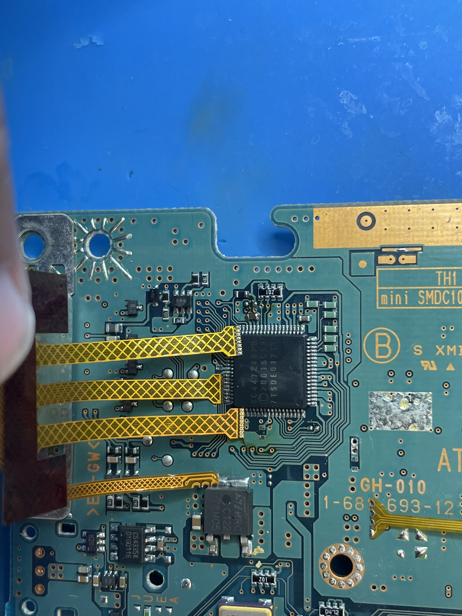
Solder the second arm.
Rotate the flex as shown.
Solder the last arm, this can be challenging.
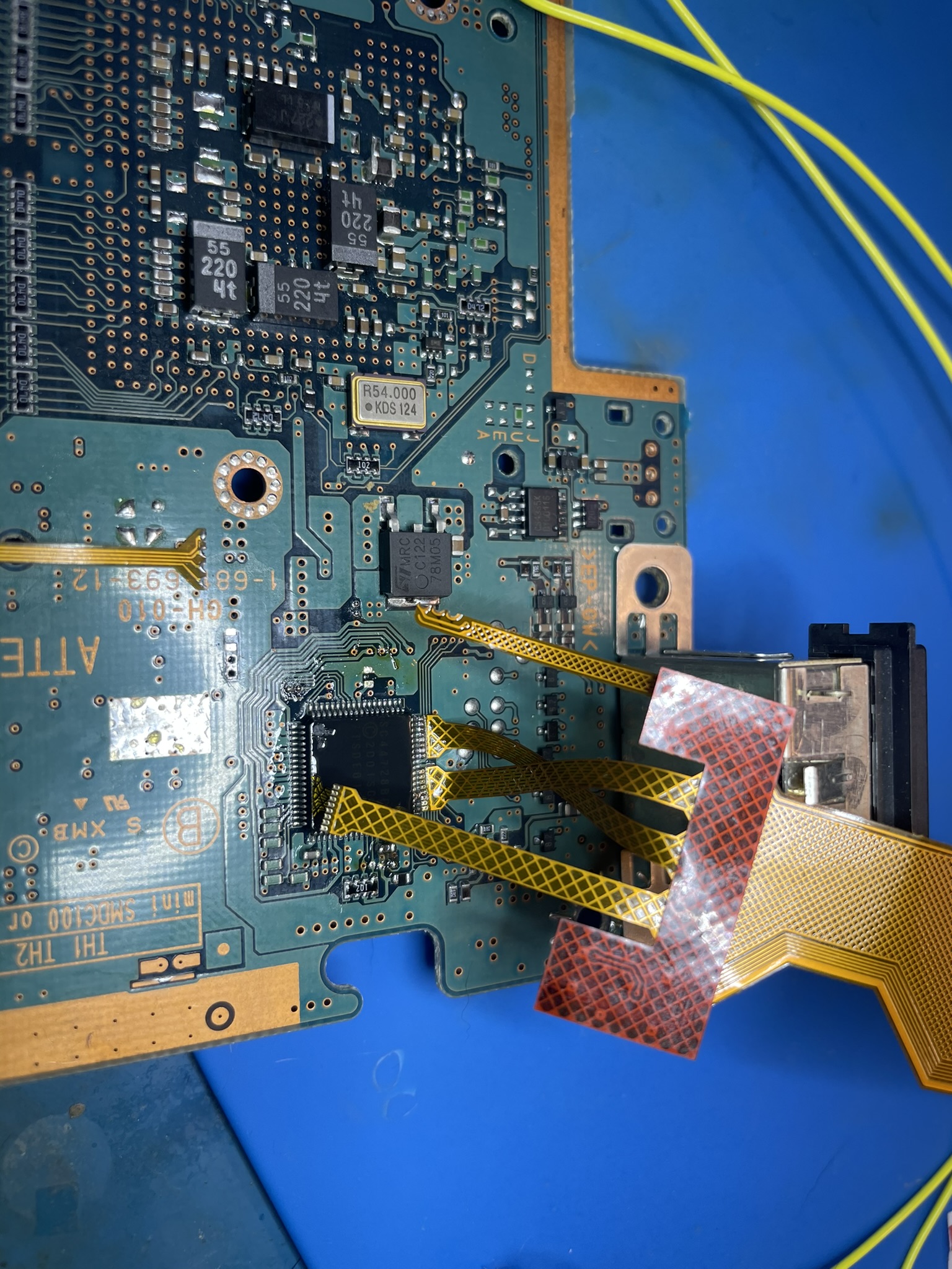
Twist and Flip the cable over so it lays flat. Tape the cable down so it does not move and solder the audio flex.
Hookup all of the points (Make sure the 3V3 jumper is solered on the flex cable). CLK, HSYNC, VSYNC, 3V3, 5V, GND.
Use 30AWG or smaller wire for the CLK/HSYNC/VSYNC
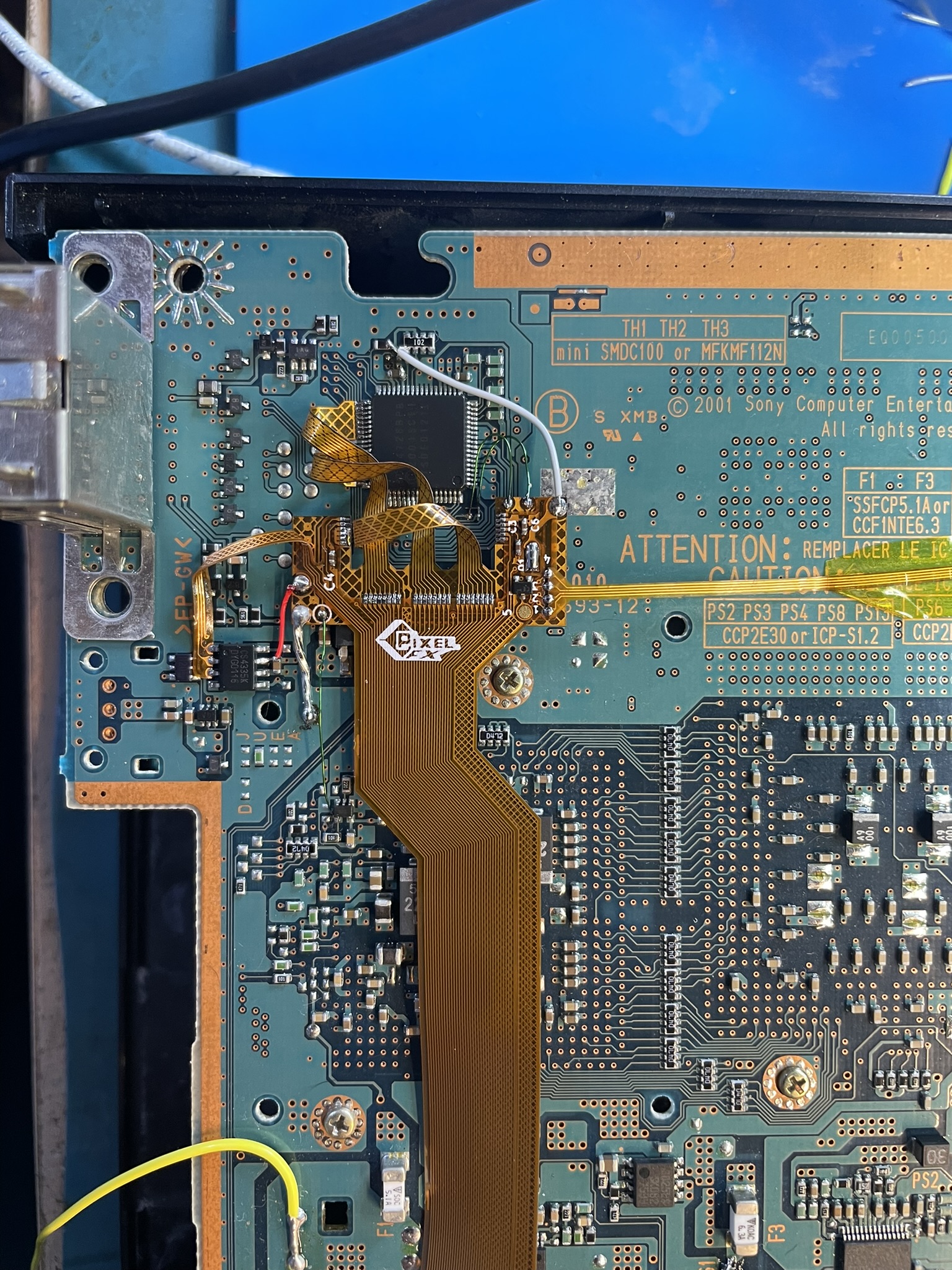
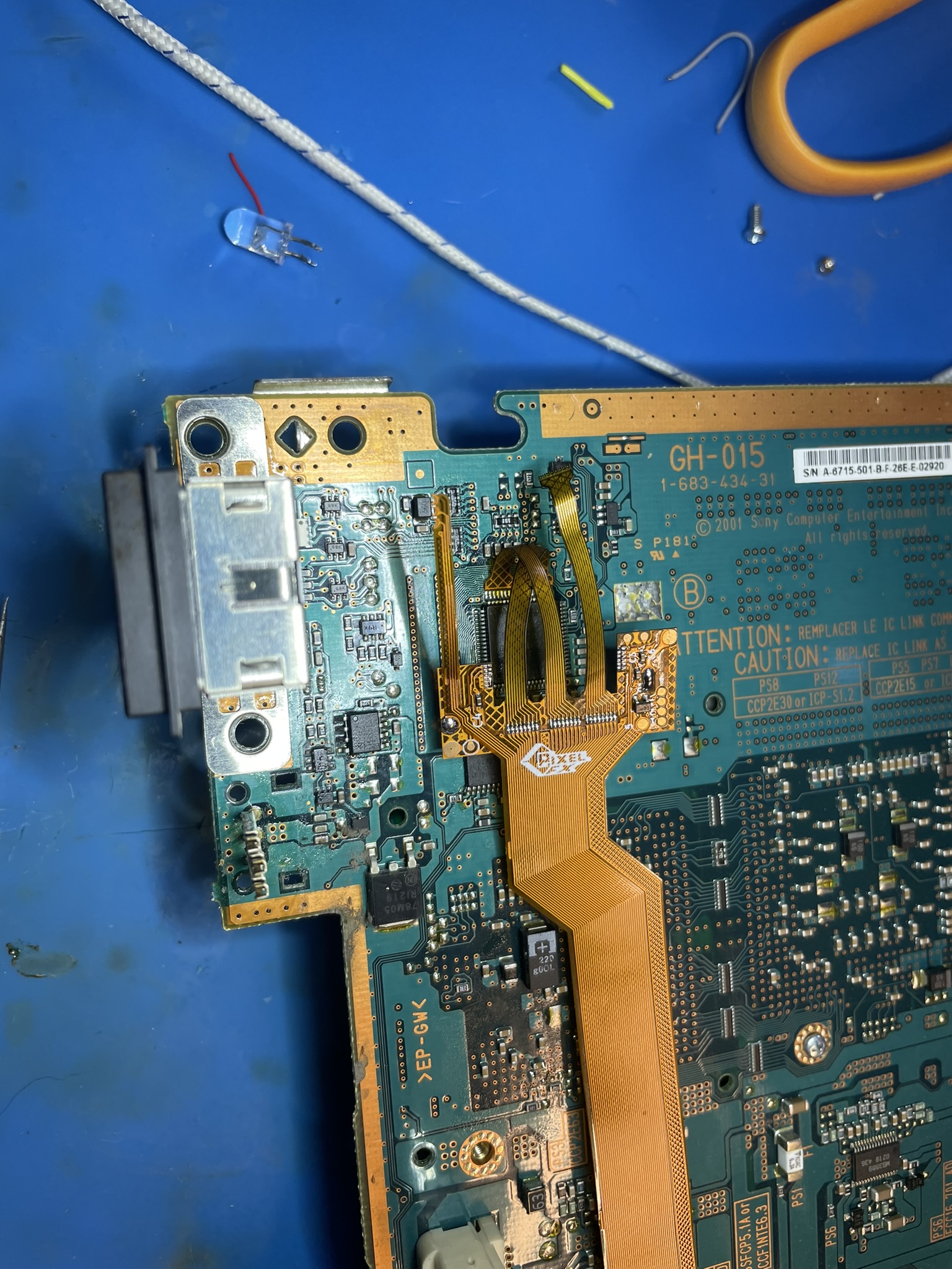
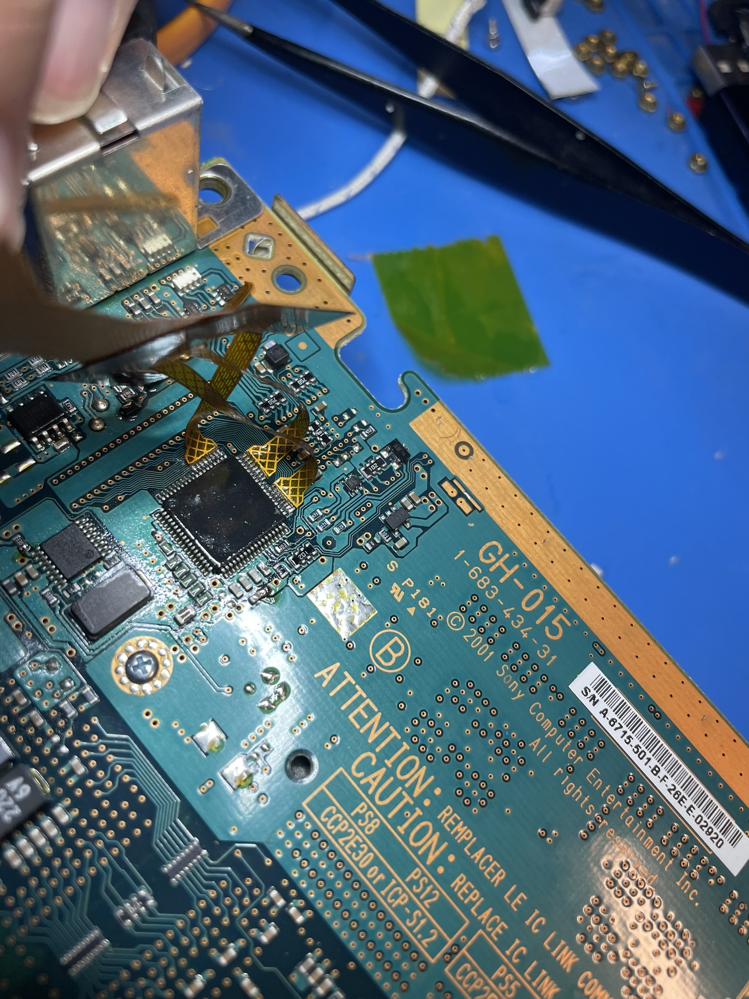
GH-015
Click to expand/collapse
Refer to the the pinout images and follow the hookups below.
Solder the first arm.
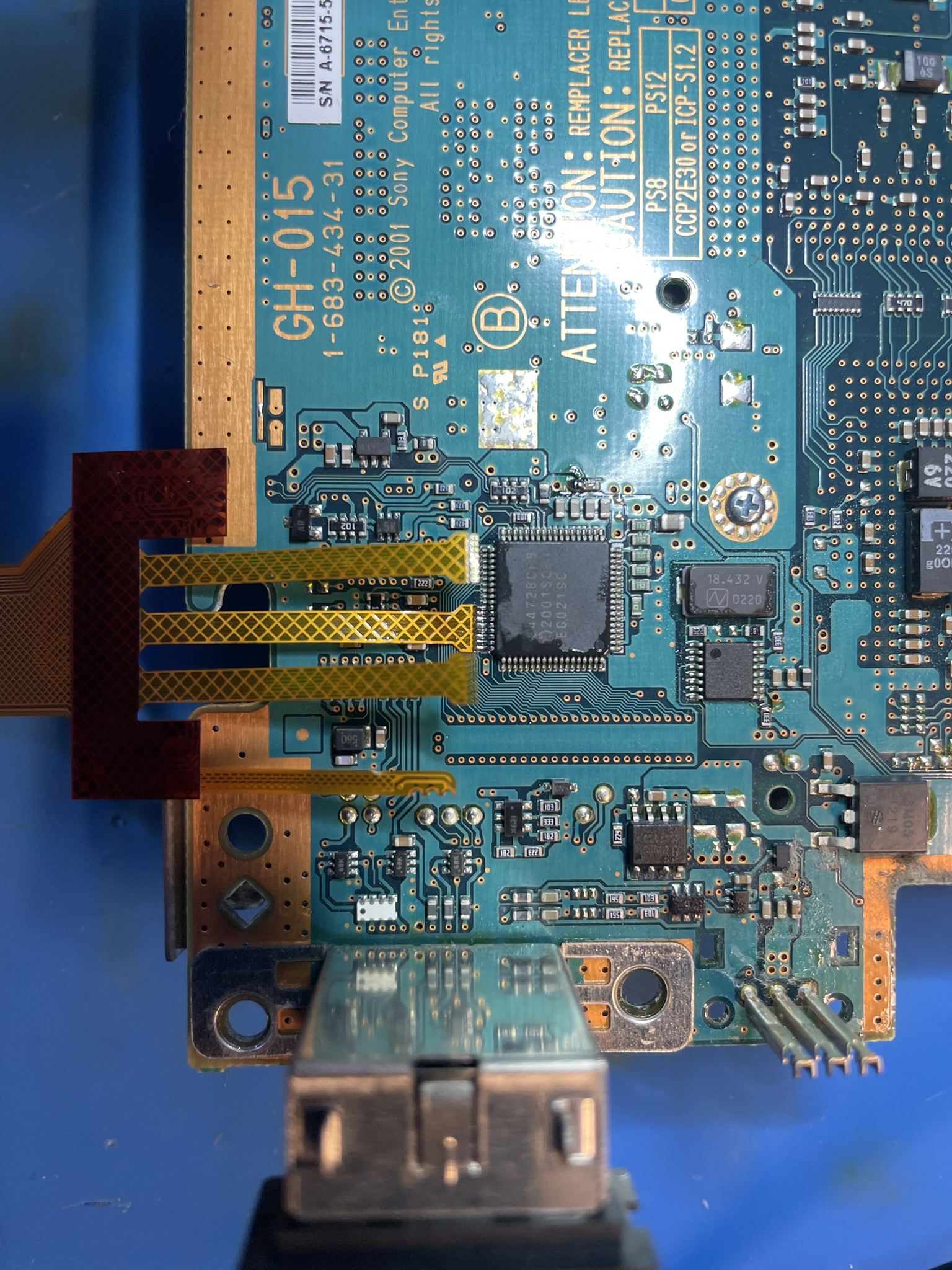
Solder the second arm.
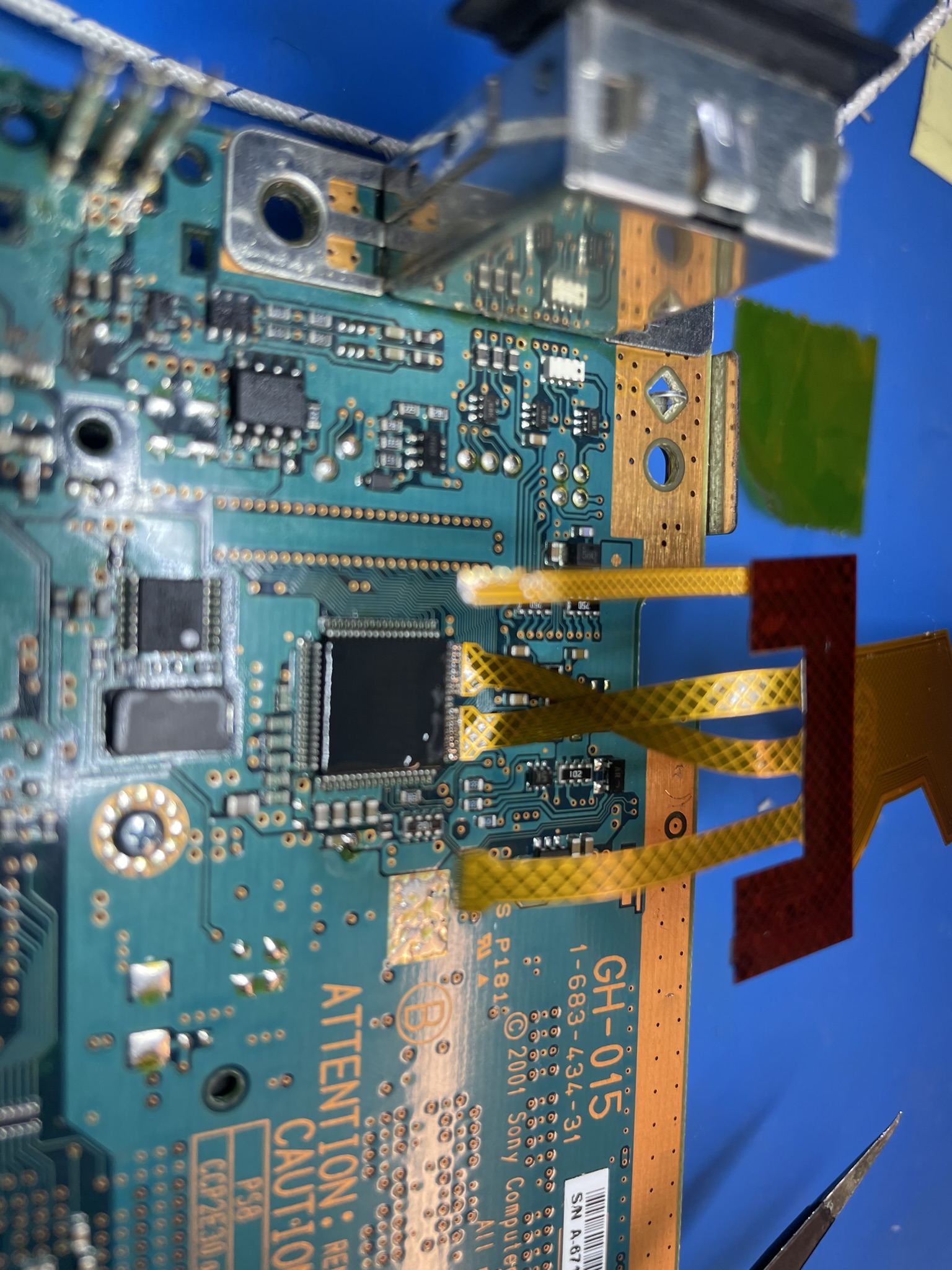
Flip the flex as shown.
Solder the last arm, this can be challenging.
Tape down the flex and solder the audio arm.
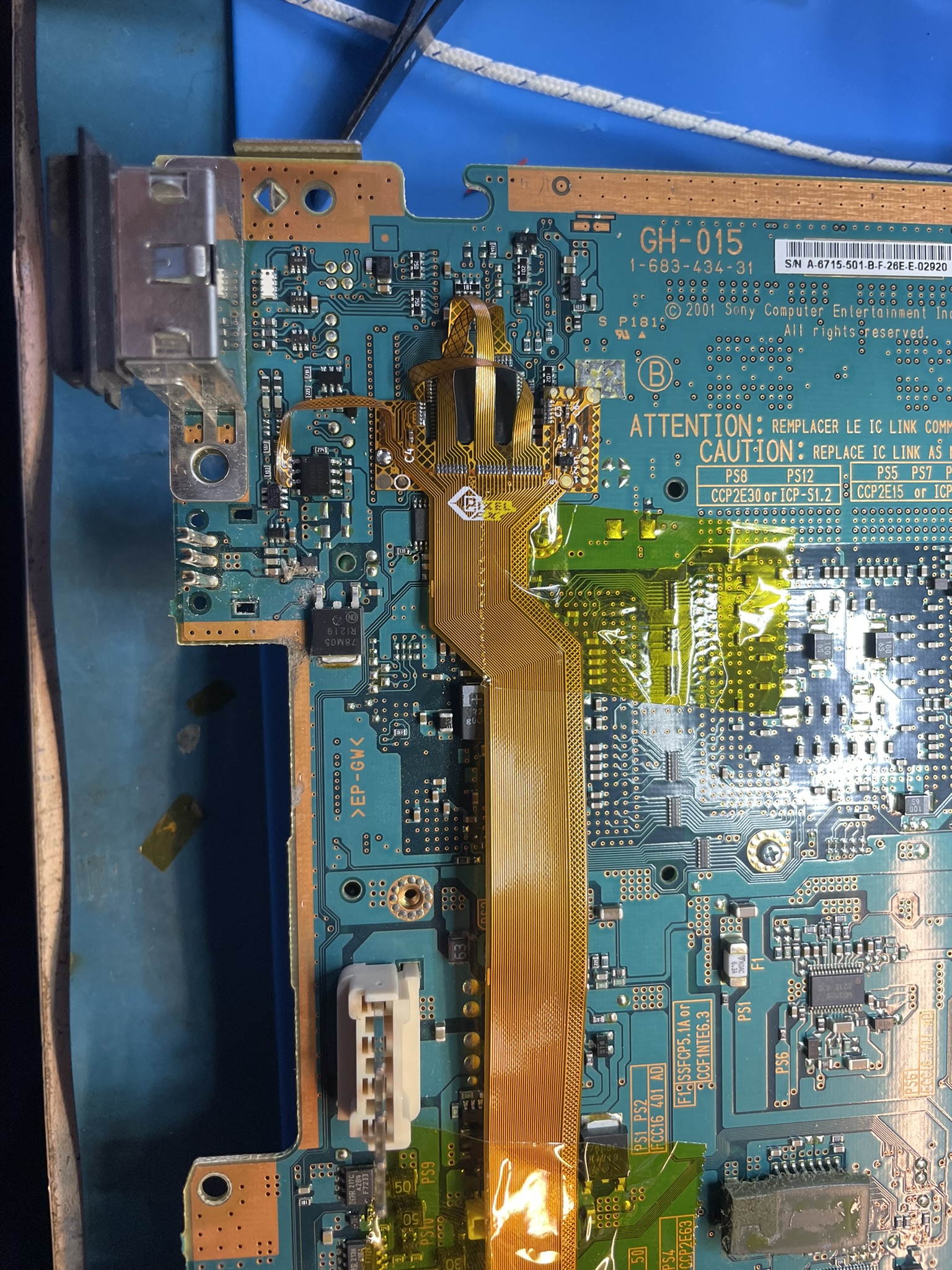
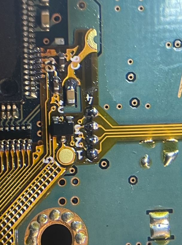
Remove some of the solder mask for the GND layer and solder the flex cable down as shown.
Hookup the rest of wires, 1V8, 5V, 3V3, CLK, HSYNC and VSYNC. Use 30AWG or smaller wire for the CLK/HSYNC/VSYNC
PAY EXTREMELY close attention to the 1V8 hook up on the flex. It is only connected to one side of the 3v3 jumper circled earlier.
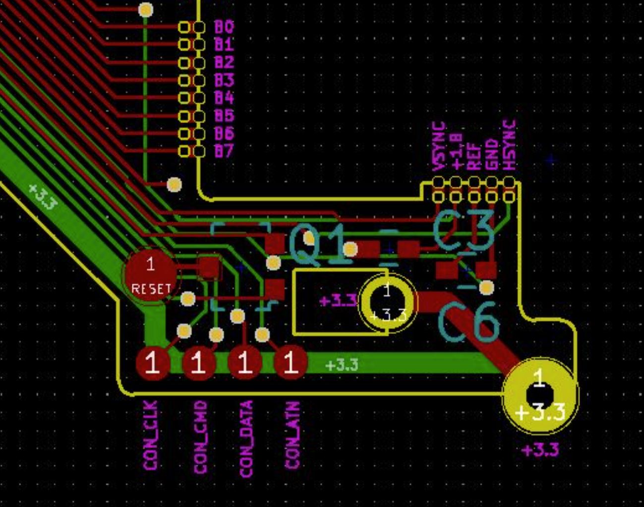
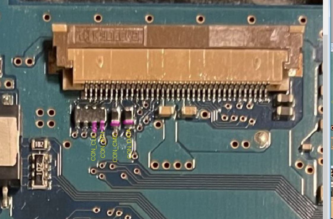
Step 3 - Installing the controller hookup.
Click to expand/collapse
There are two ways to setup the controller hookup. Using the supplied flex or with wires. The flex pinout is the same on all motherboard revisions. Sometimes there are in components in the way that make soldering the flex even harder.
You should only attempt to do the flex method if you have a stereoscopic microscope. Its difficult to solder so using 30AWG solid core wire is also recommend.
If you plan to use wires for your controller installation you must update the firmware on the retro GEM after installation. The controller might not work initially, and this is expected with wires. You can update your firmware to the latest firmware using a CEC (Your TV remote), or the rescue system.
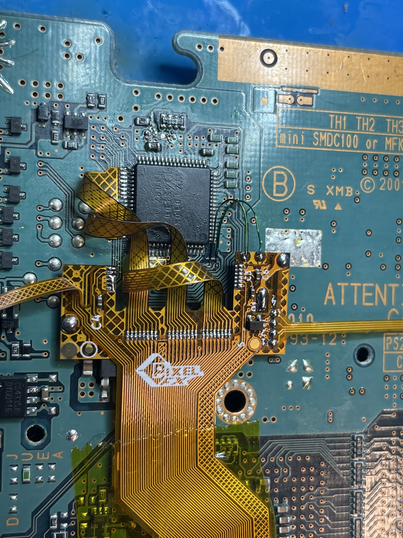
FLEX
Click to expand/collapse
Align the flex and solder into place. Confirm the traces are on the flex are facing up.
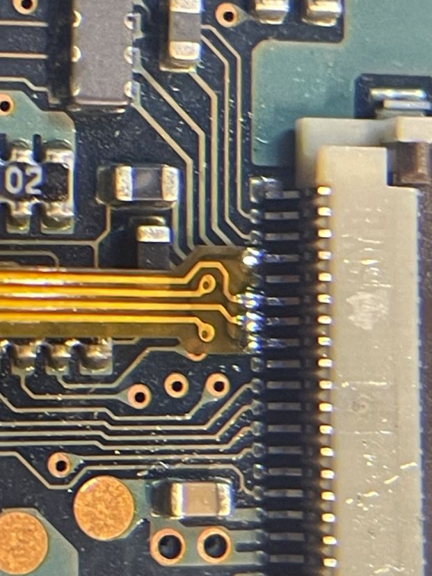
Align the controller flex on the main flex and solder into place. (Make sure the traces are facing up)
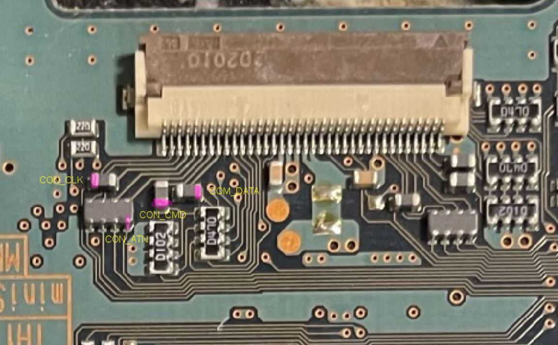
Wires
Click to expand/collapse
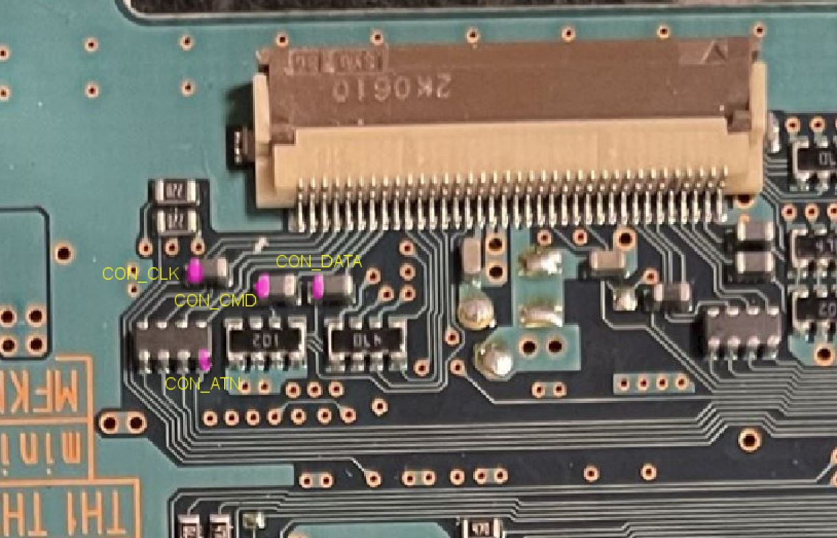
Refer to your motherboards pin out and run wires from each alternative place to the main flex.
GH-019
GH-022
GH-023
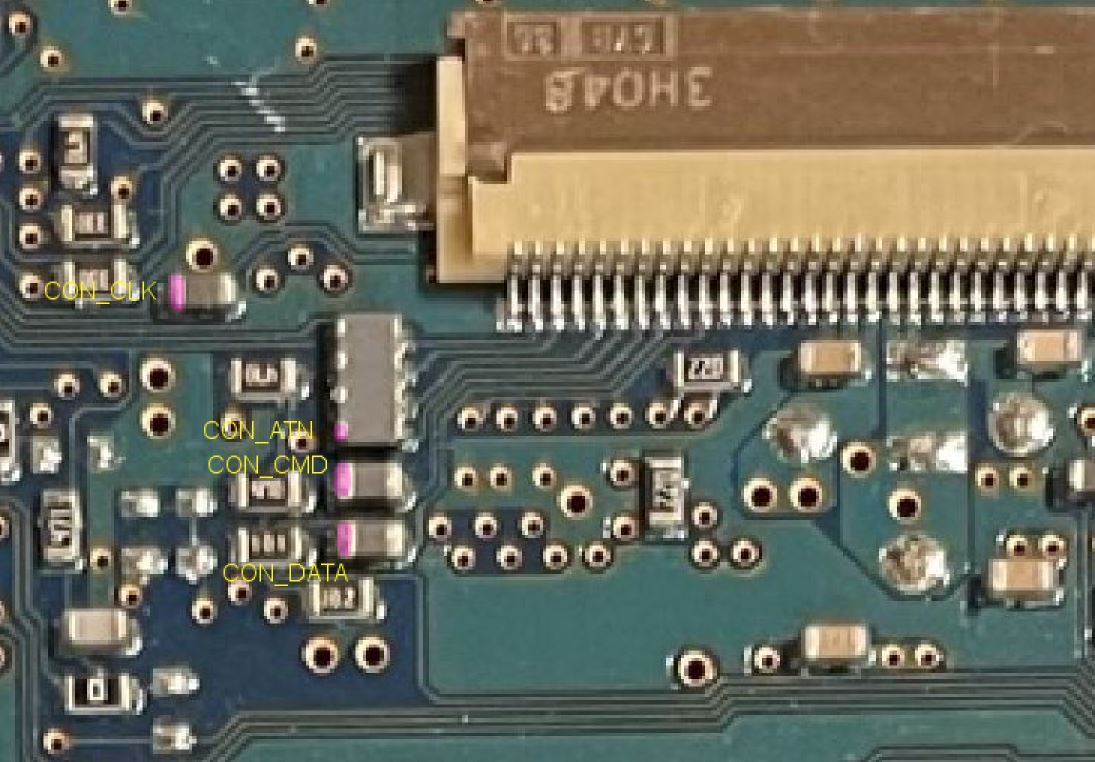
GH-026
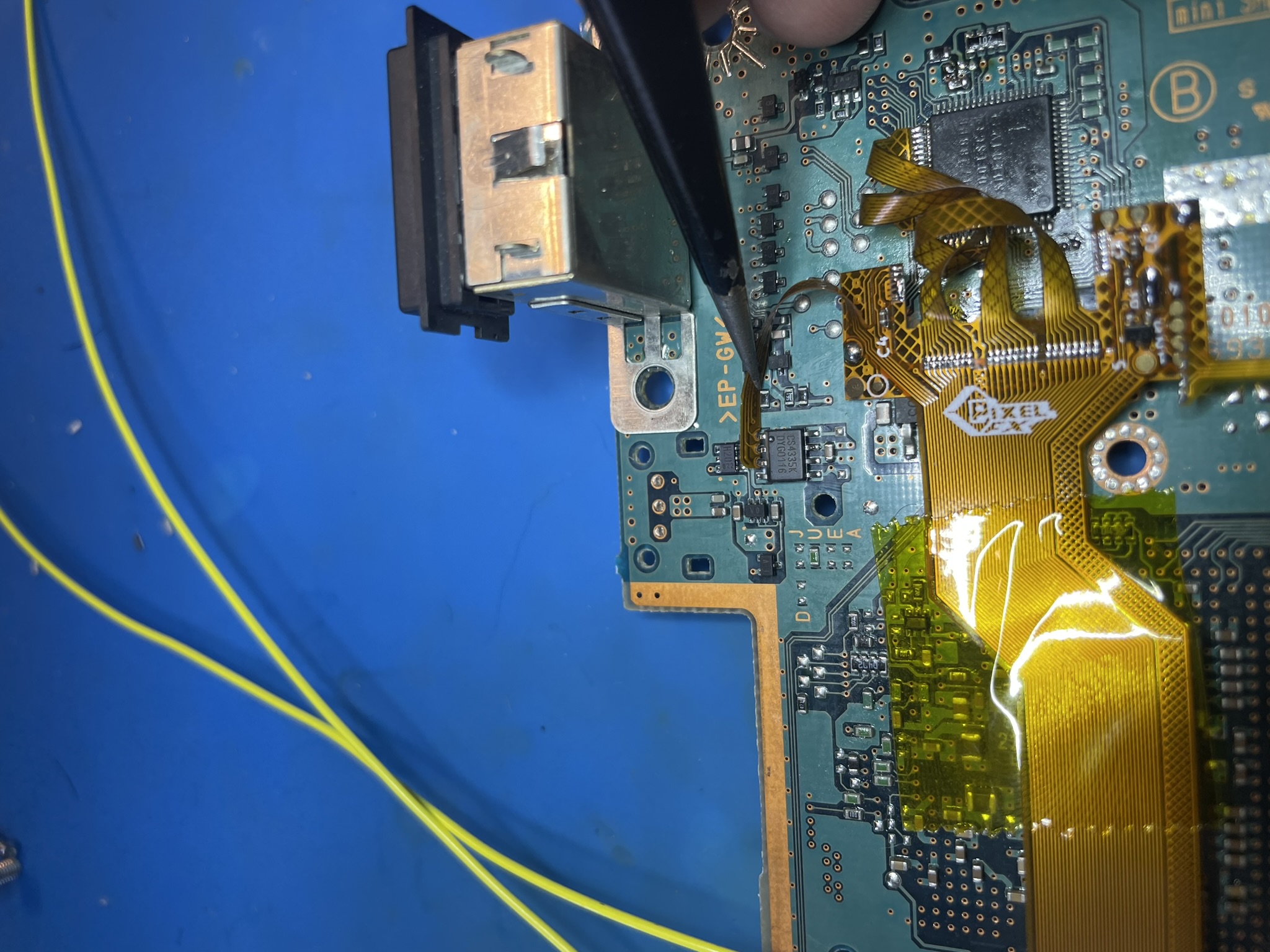
Step 4 - Installing the reset line
Click to expand/collapse
Run a line from the reset test point to the point on the flex.
Refer to your motherboard below:
GH-010
GH-015
GH-019
GH-022
GH-023
GH-026
Step 5 - Testing
Click to expand/collapse
Its possible to test the console with it partially dissaembled. Be extremely careful, there will be live a/c mains.
Before testing its highly recommend you test each pin to verify no pins are bridged. Use the pinouts page for support.
Partial shorts (100ohm) are expected between ground and the power rails from bleed off resistors.
Before attaching the retro gem confirm the analog/composite video still work correctly. If you have any problems with composite this will signify you have bridged or discconneted pins.
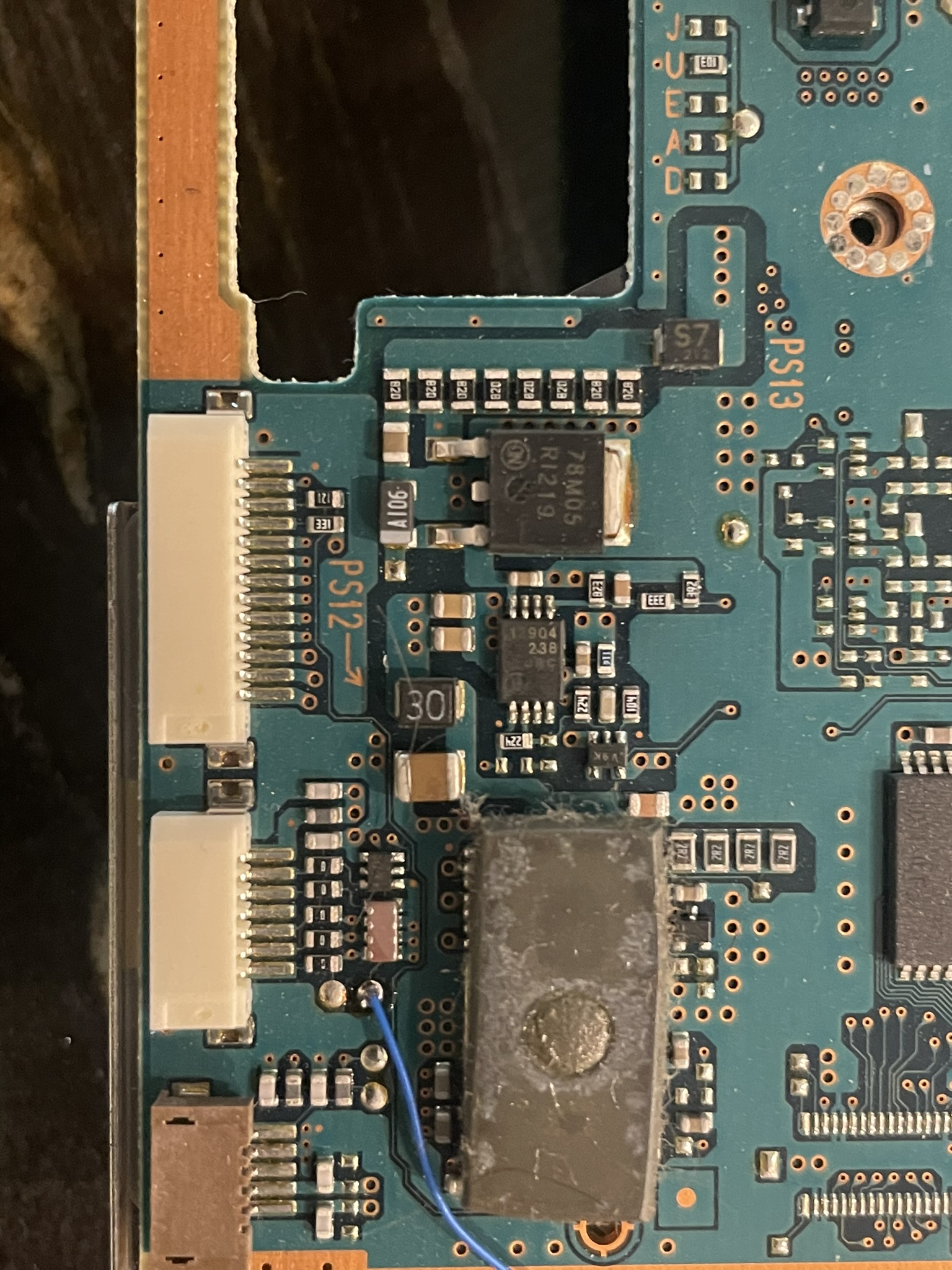
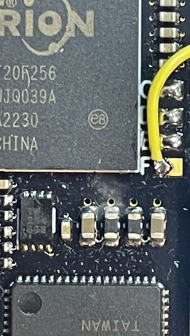
Step 6 - Installing the SPDIF line
Click to expand/collapse
For DTS and Dolby sound needs a special wire routed to the retro GEM. After removing the SPDIF port solder a small 6in wire as shown:
We will solder the other end of this wire after the GEM board is mounred.
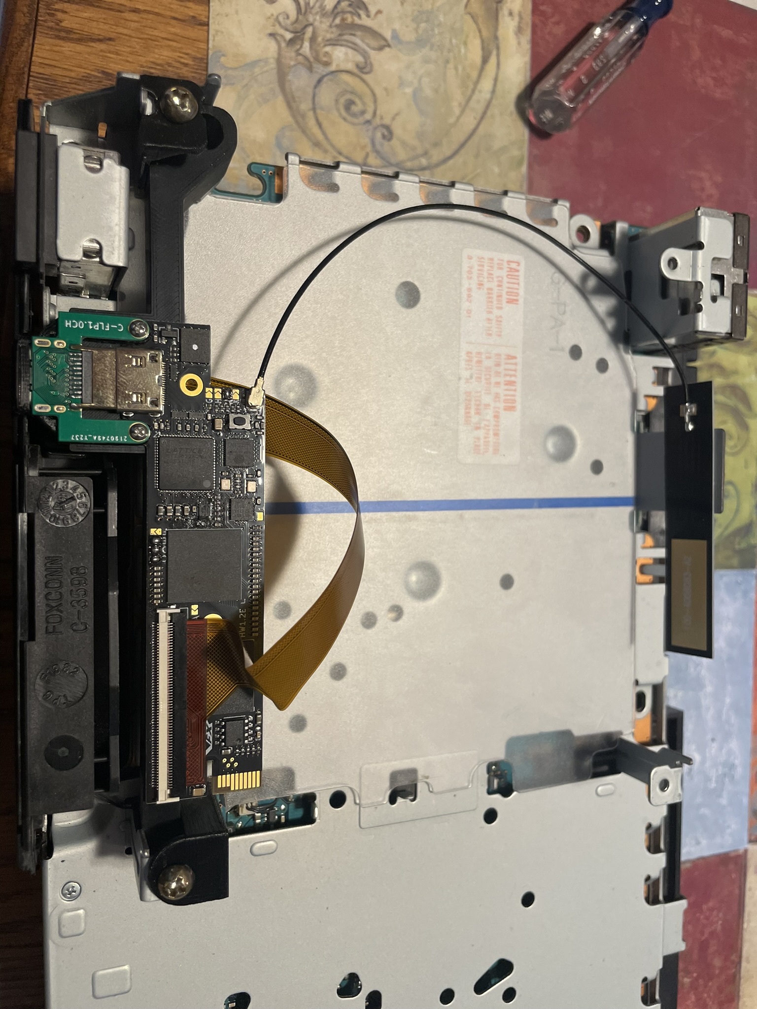
Step 7 - Mounting the GEM Board
Click to expand/collapse
Bend the main flex as shown.
Break apart the Plastic Panel
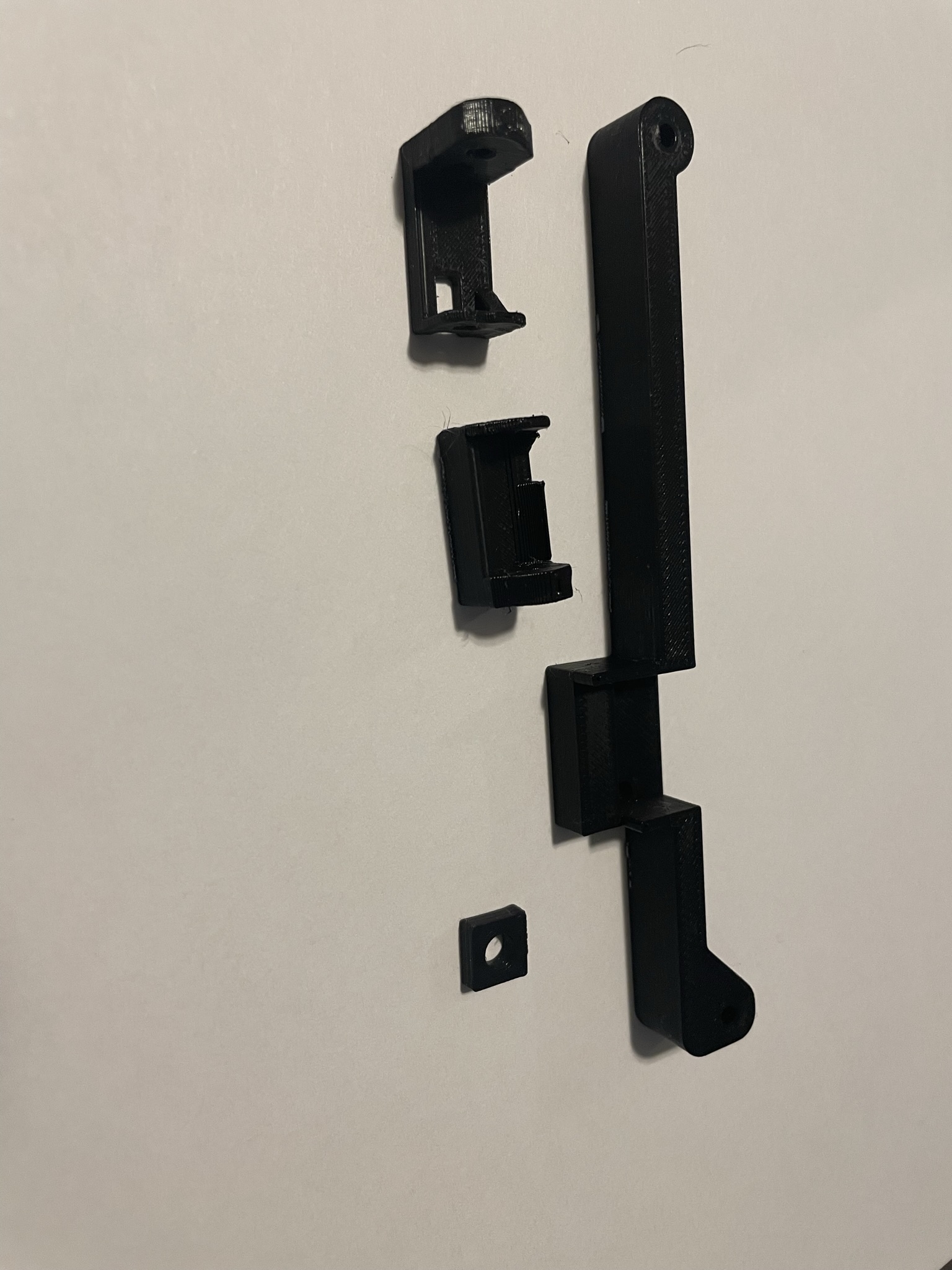
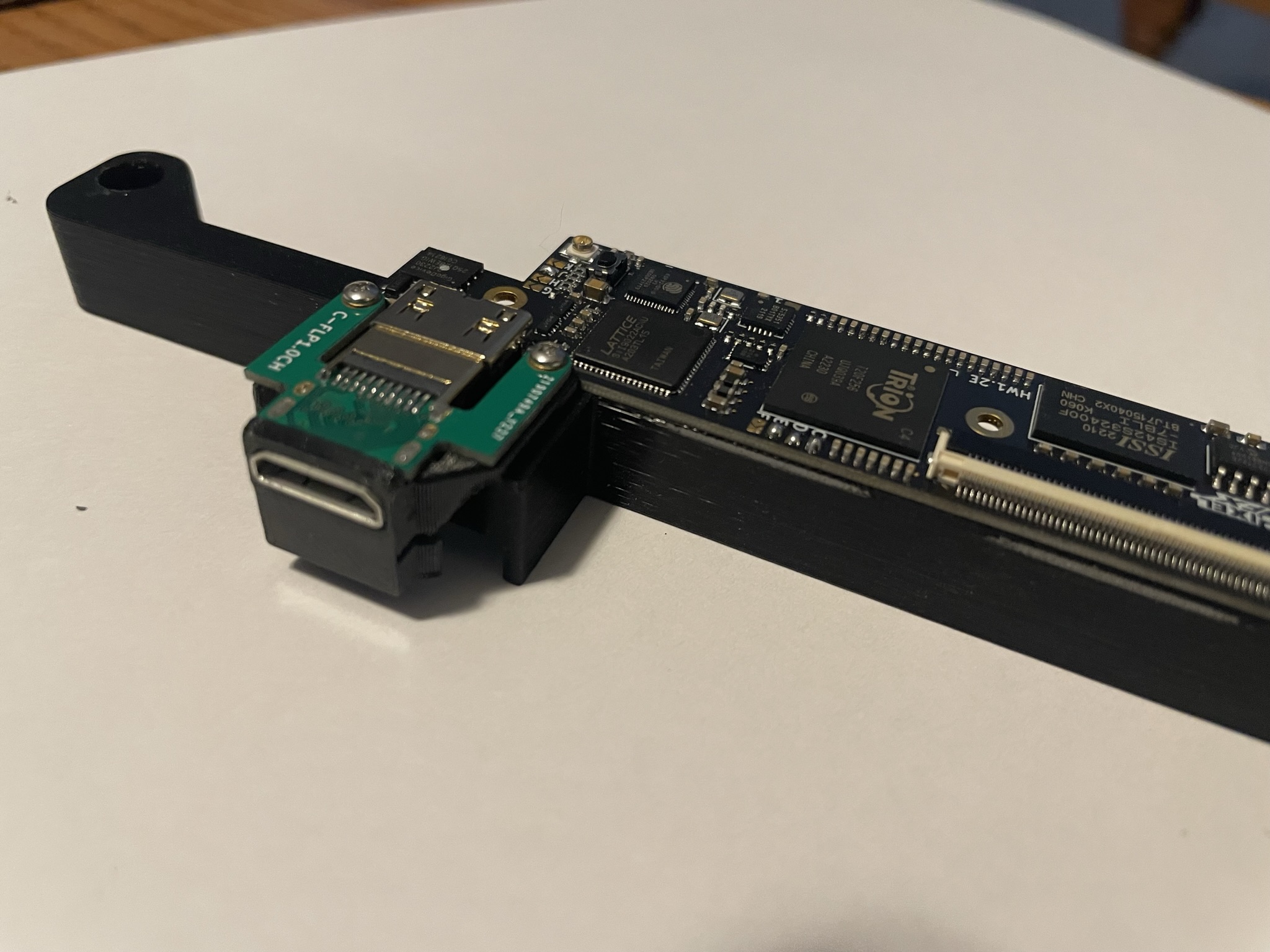
Attached the HDMI extention and cover to the mount as shown. Use the M1.6 screws and nuts. Do not overtighten.
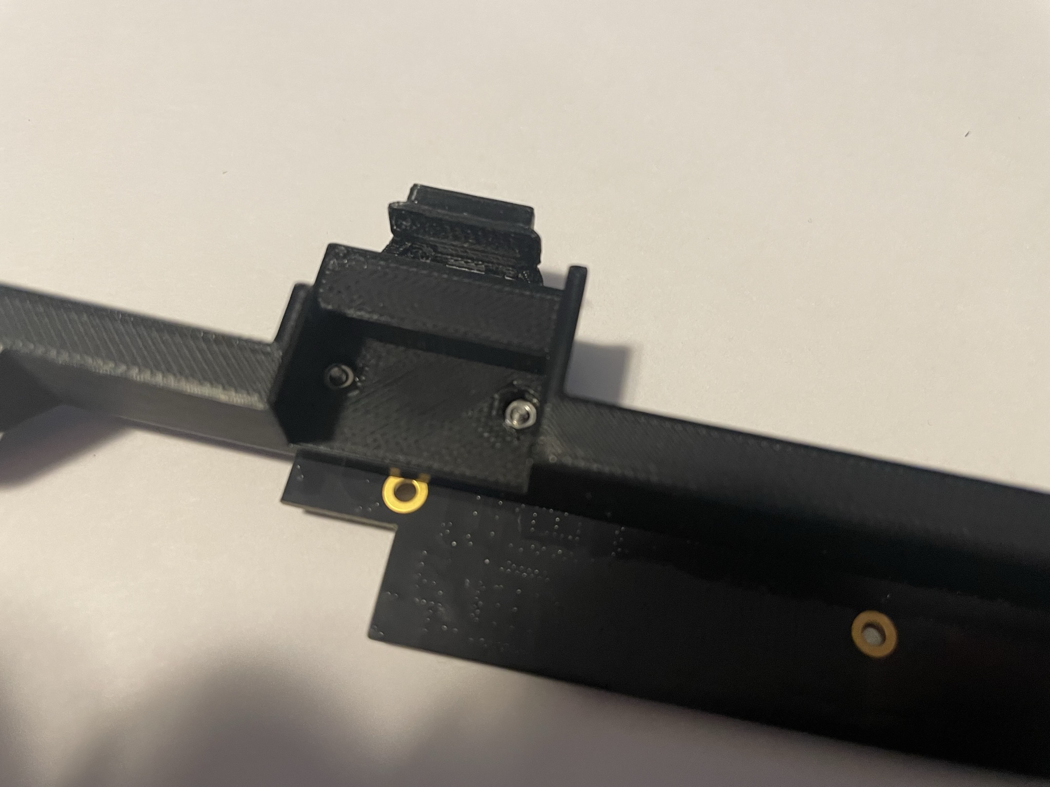
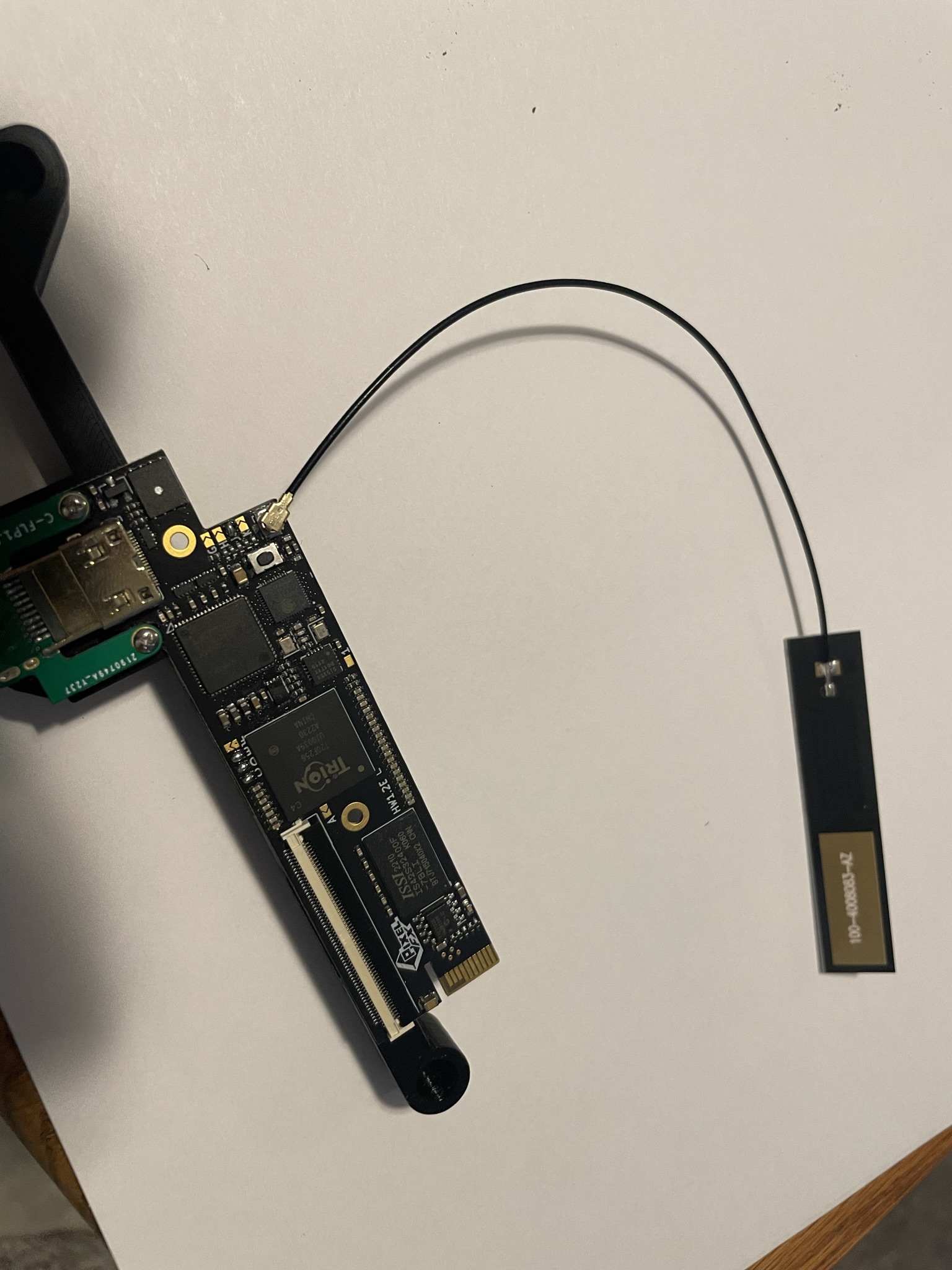
Attach the Antenna
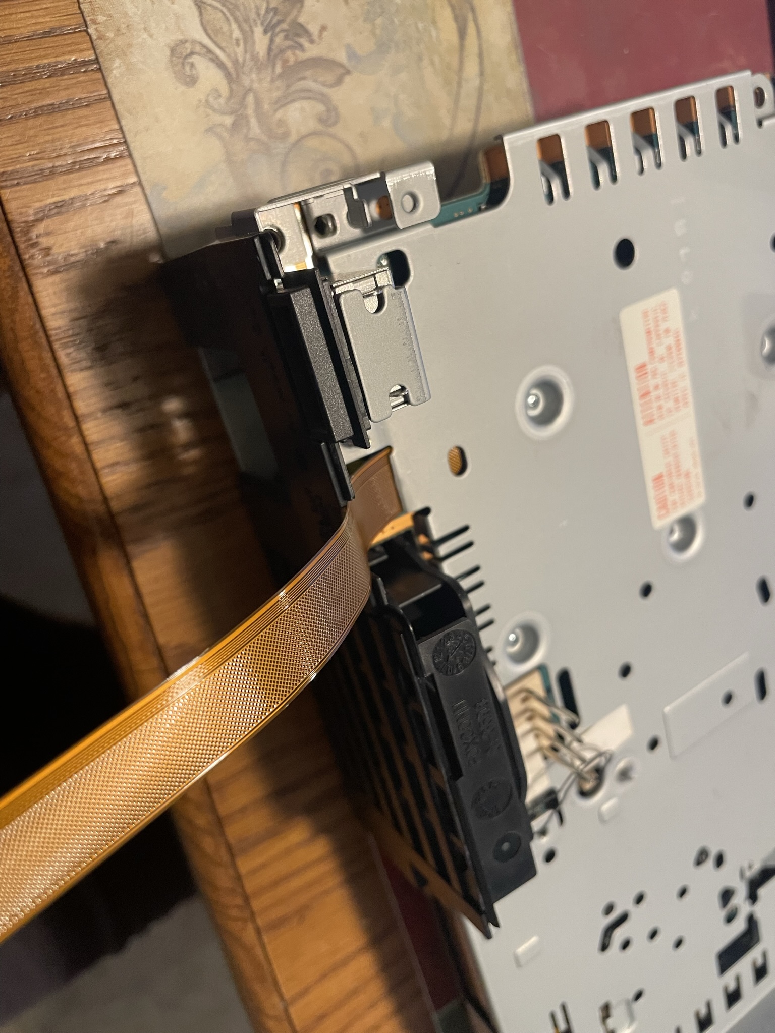
Remove the Toslink support mount on the metal shield:
Choose your model:
SCPH-5000X
Click to expand/collapse
Attach the top and bottom metal shield. Make sure to use the small spacer supplied with the 3D prints
![]()
![]()
Attach the fan and mount:
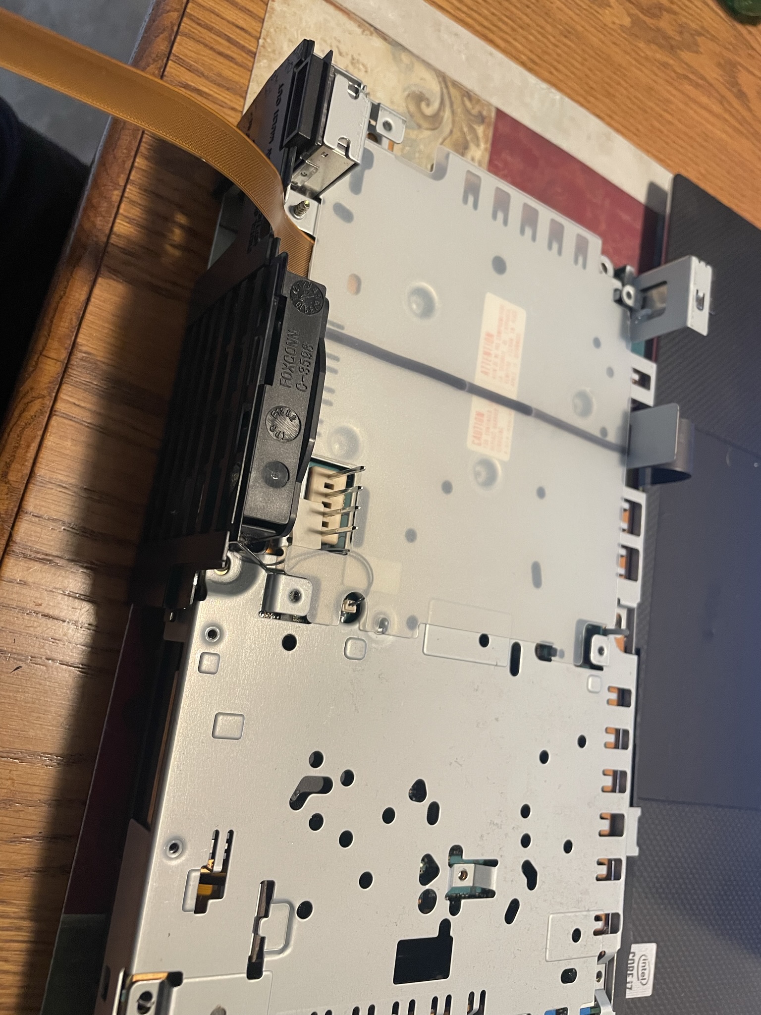
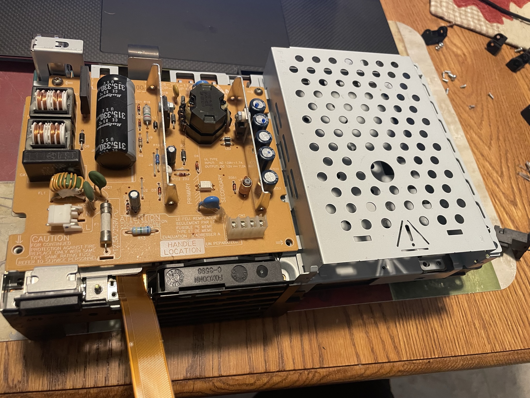
Mount the power supply (don't forget the plastic insulator) but do not screw it into place. Test fit the GEM board. Some power supplies might have a metal shield or components that are in the way. The components can be tilted out of the way. If you have one with the heatsink shield in the way, this will have to be cut.
Make sure the flex cable routes under the retro GEM mount
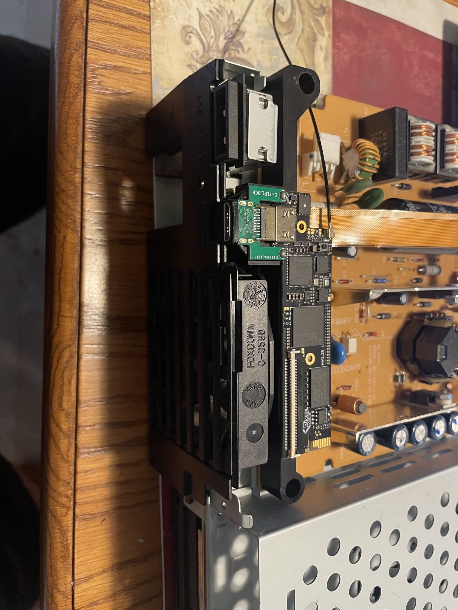
Secure both the power supply and retro gem with the oem screws.
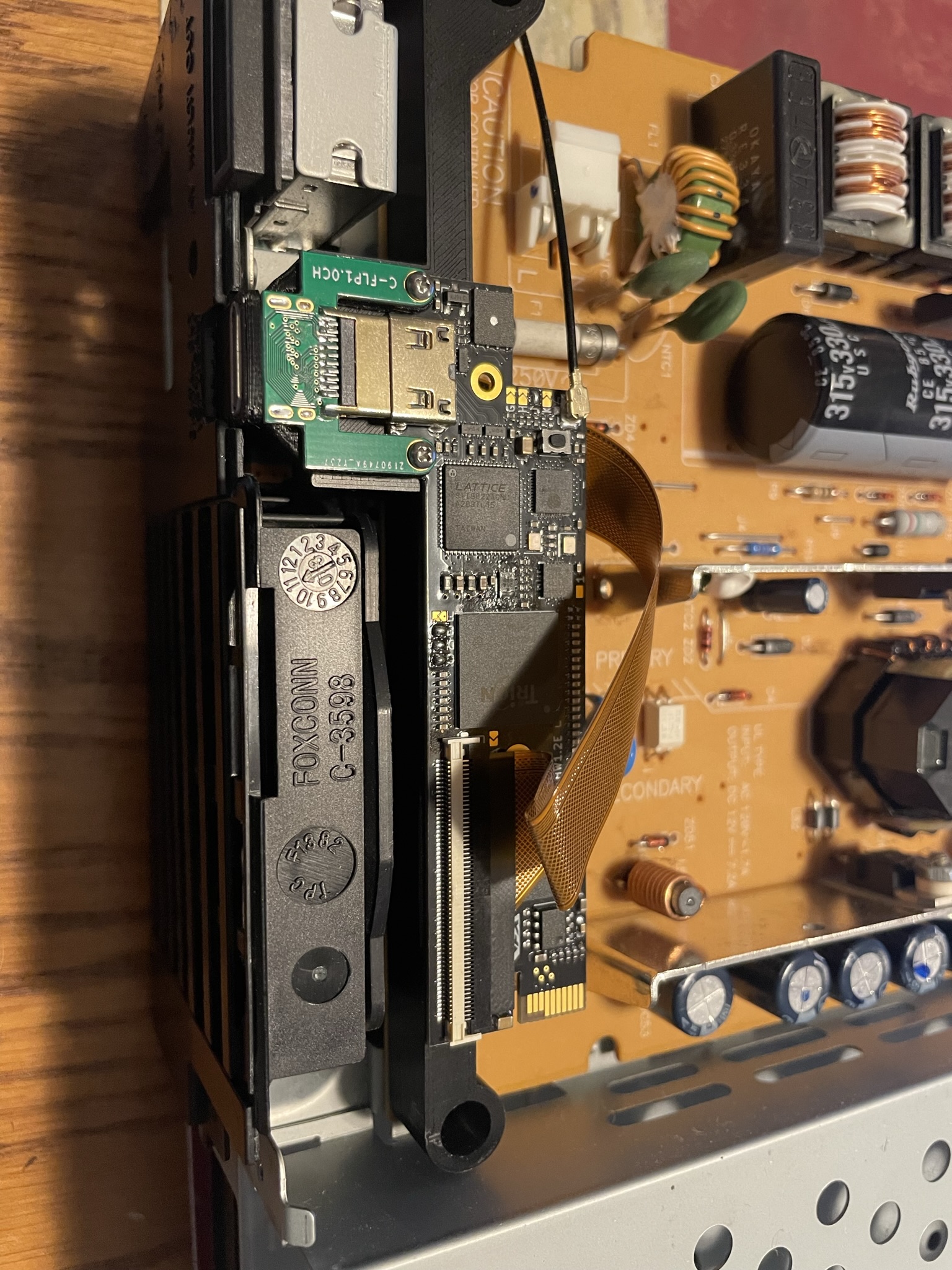
Route the flex cable as shown and insert into the FFC of the Retro GEM.
Attach the Antenna as shown
SCPH-3900X w/ SCPH-5000X power supply & Shield
Click to expand/collapse
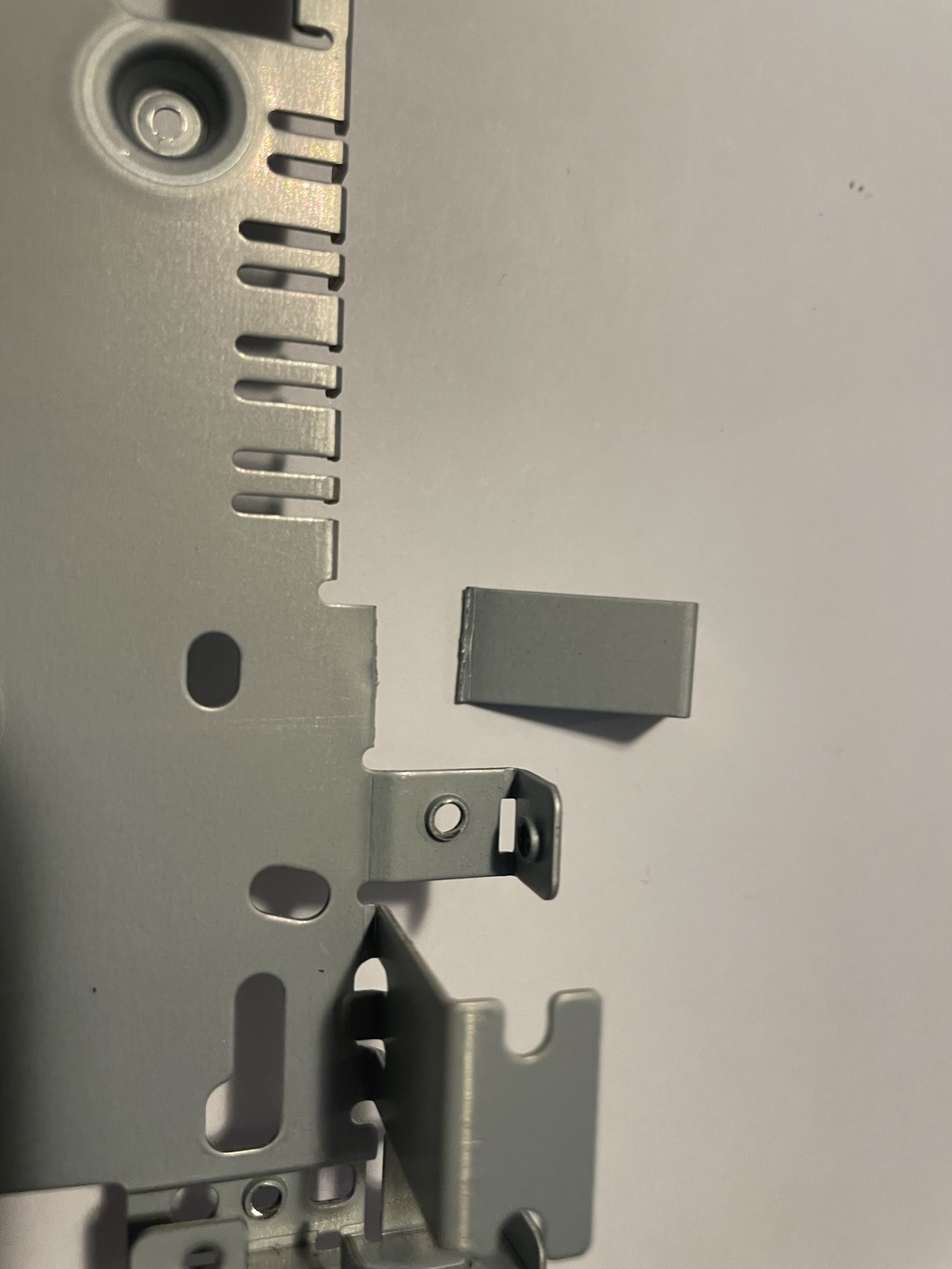
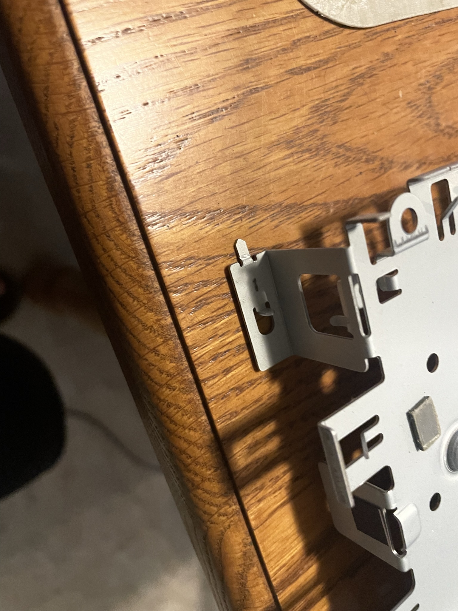
The 5000x shield shield needs this small tab bent flat:
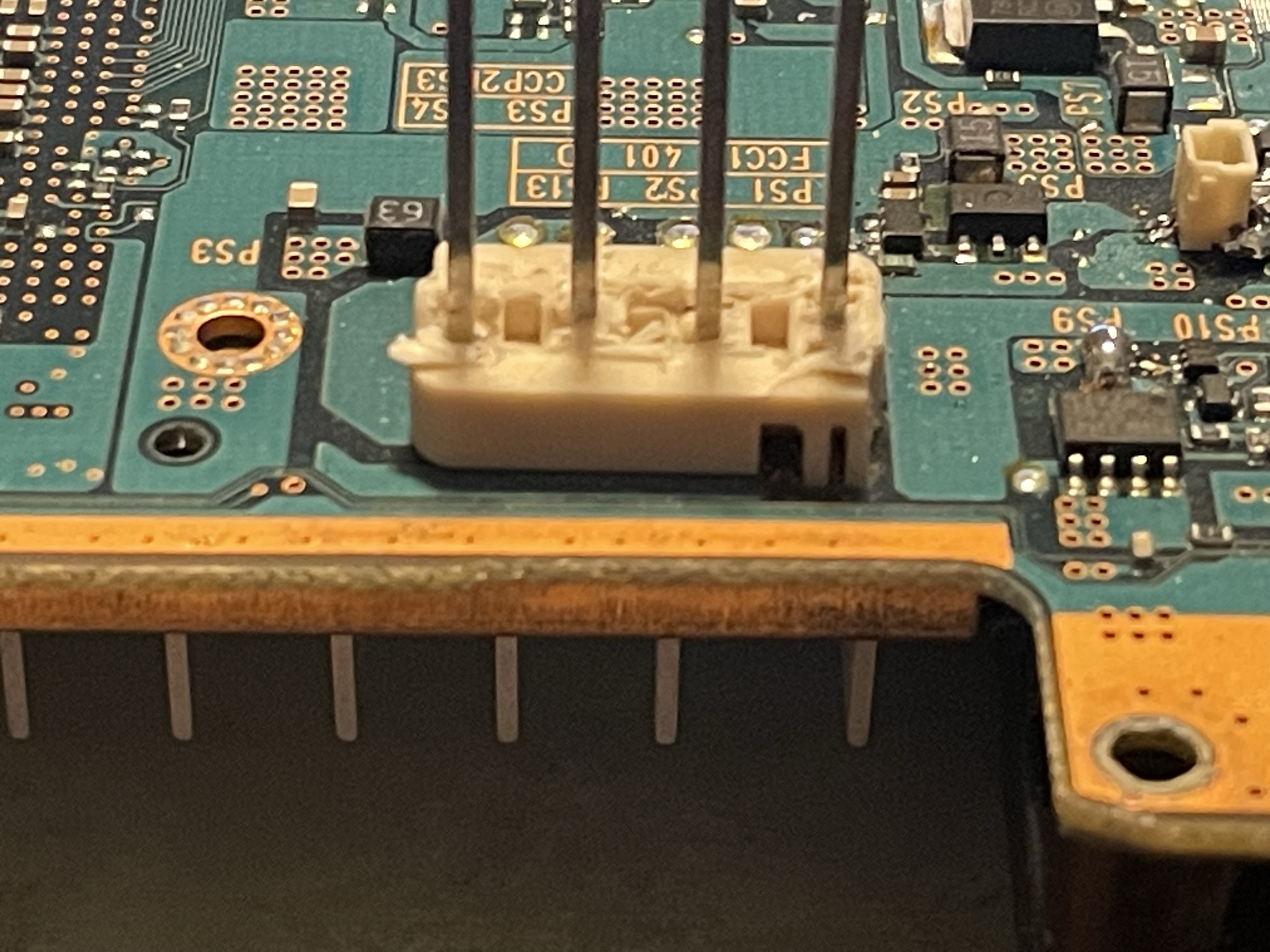
The power connector plastic on the mainboard needs to be trimmed as shown (Do not cut the pins):
Attach the top and bottom metal shield. Make sure to use the small spacer supplied with the 3D prints
![]()
![]()
Attach the fan and mount:
Mount the 5000x power supply (don't forget the plastic insulator) but do not screw it into place. Test fit the GEM board. Some power supplies might have a metal shield or components that are in the way. The components can be tilted out of the way. If you have one with the heatsink shield in the way, this will have to be cut.
Make sure the flex cable routes under the retro GEM mount
The power supply pins need to be cut shorter so it does not make contact with the gem board. After install the power supply. Trim the pins.
Secure both the power supply and retro gem with the oem screws.
Route the flex cable as shown and insert into the FFC of the Retro GEM.
Attach the Antenna as shown
SCPH-3900X with REPS2 or similar power supply
Click to expand/collapse
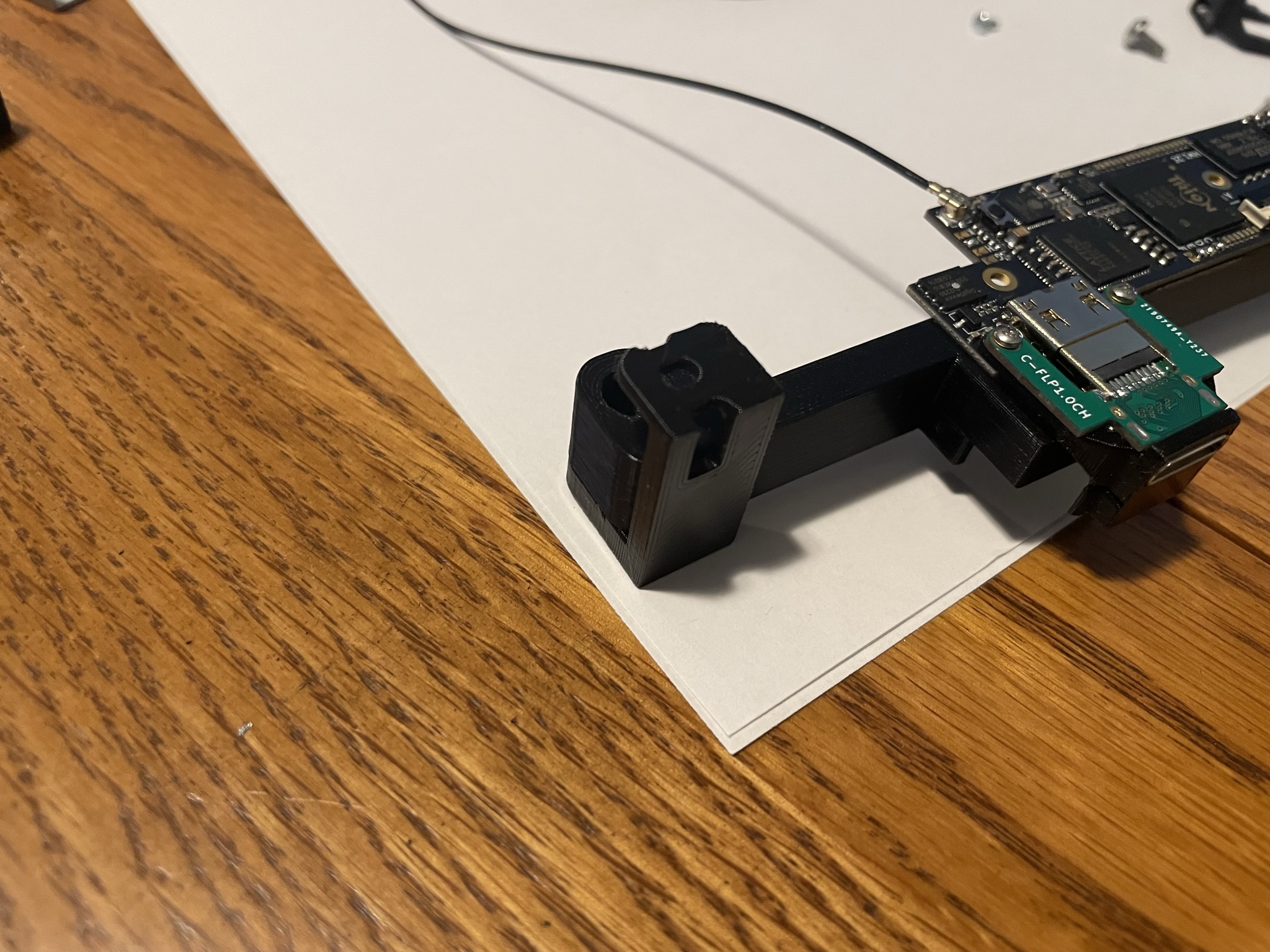
Attached the 39000x mount feet using the supplied M3 nuts and screws. You will need a P0 Screw driver to fit inside the 3d printed hole.
Use the longer M3 screw with this mount:
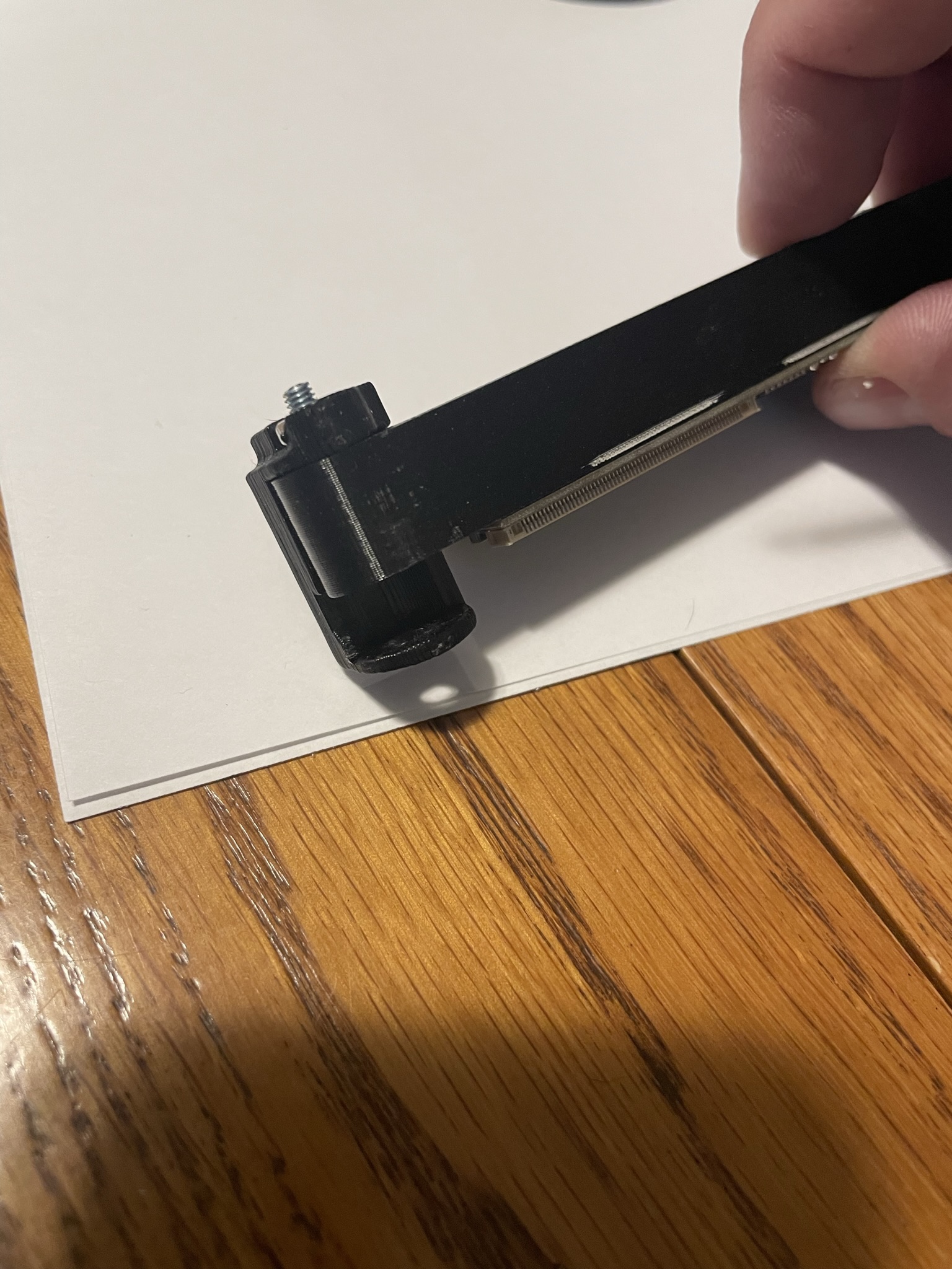
Use the shorter M3 screw with this mount.
Attach the top and bottom metal shield. Make sure to use the small spacer supplied with the 3D prints
![]()
![]()
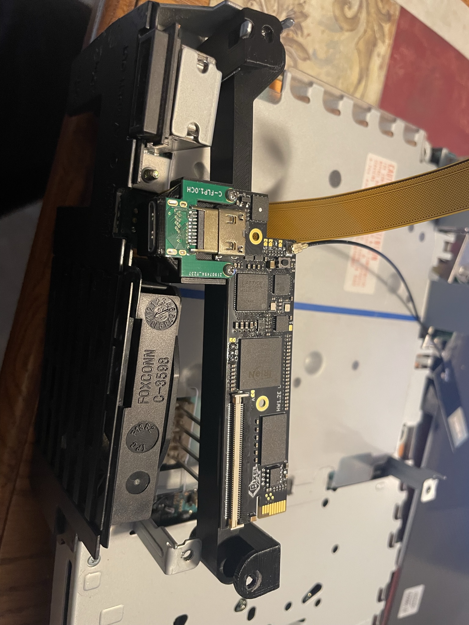
Install the REPS2 or similar device now. Do not forget the flat plastic insulator.
The power supply pins need to be cut shorter so it does not make contact with the GEM board. After install the power supply. Trim the pins.
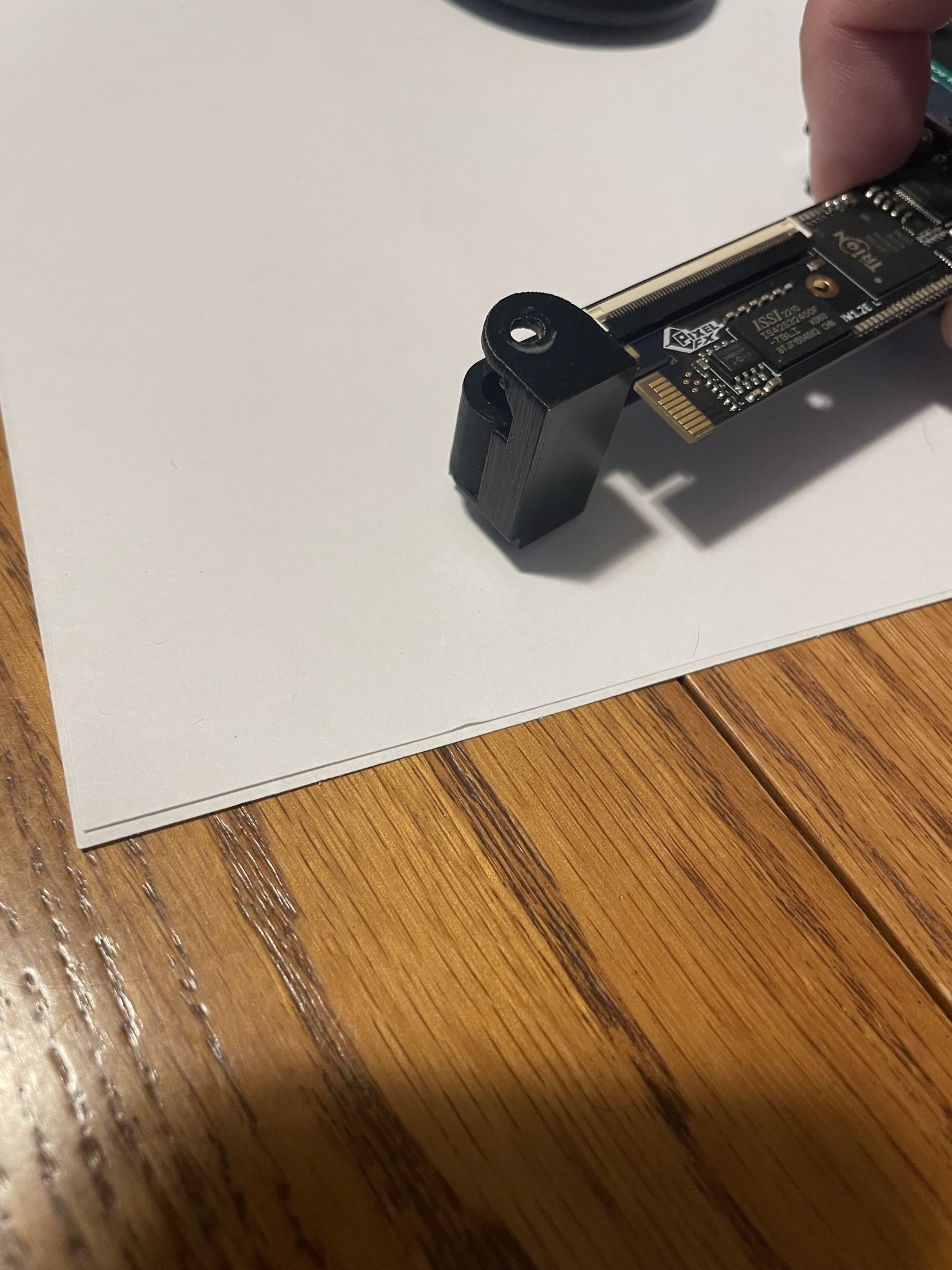
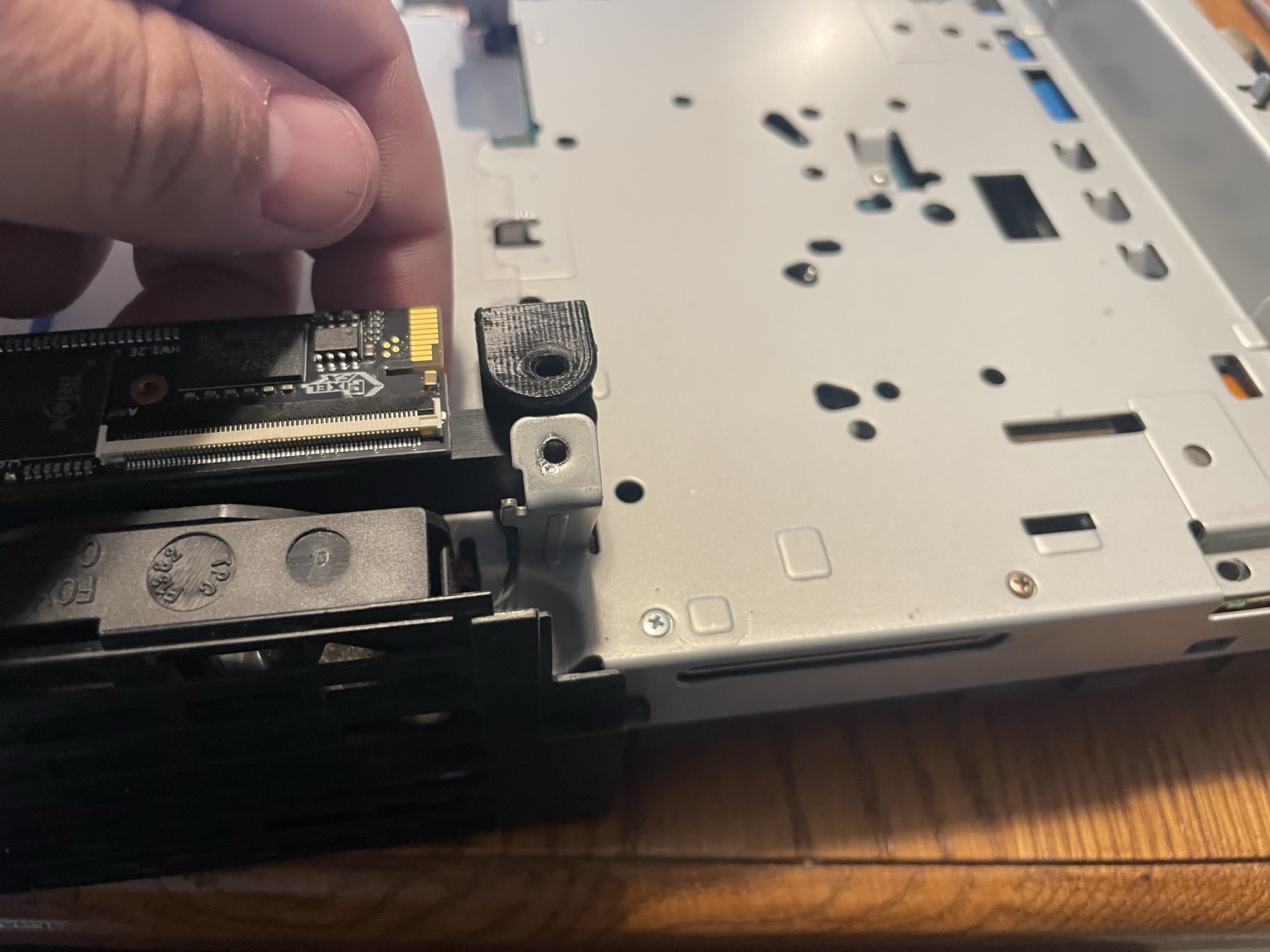
Install the GEM board as shown. Bend the arm on the right so the gem can slide in. Push the arm back in place and secure the GEM using the OEM power supply screws.
Make sure the flex cable routes under the retro GEM mount
Step 8 - Finishing up the SPDIF wire
Click to expand/collapse
Install the other end of the SPDIF wire to the GEM board on PIN 1 of Jumper F.
Now would be another good time to test the installation and make sure everything is working well. All that is needed is the basic Reassembly.