Retro GEM PS1 Installation Instructions
Disclaimer: This kit is for advanced installers only. Install at your own risk. We cannot be held responsible for damage to your console and/or kit. Each kit is individually tested and confirmed working before being shipped.
Before you begin:
The kit is compatible with PU-18 (SCPH-550X) and PU-20 (SCPH-700X) motherboards. PU-22 and PSOne support will likely added in the future.
Kit includes:
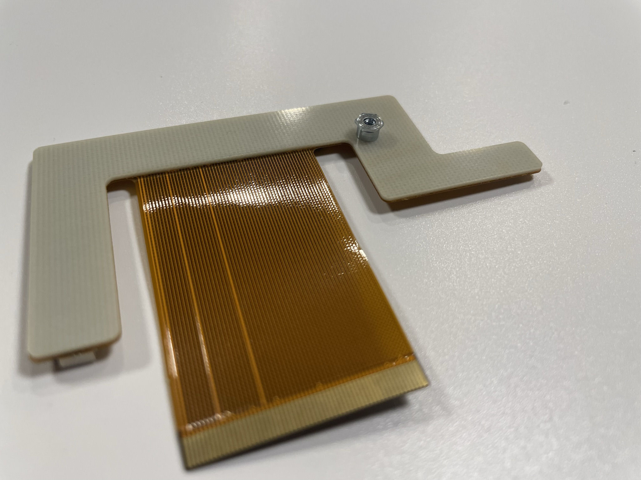
- PS1 Flex Panel
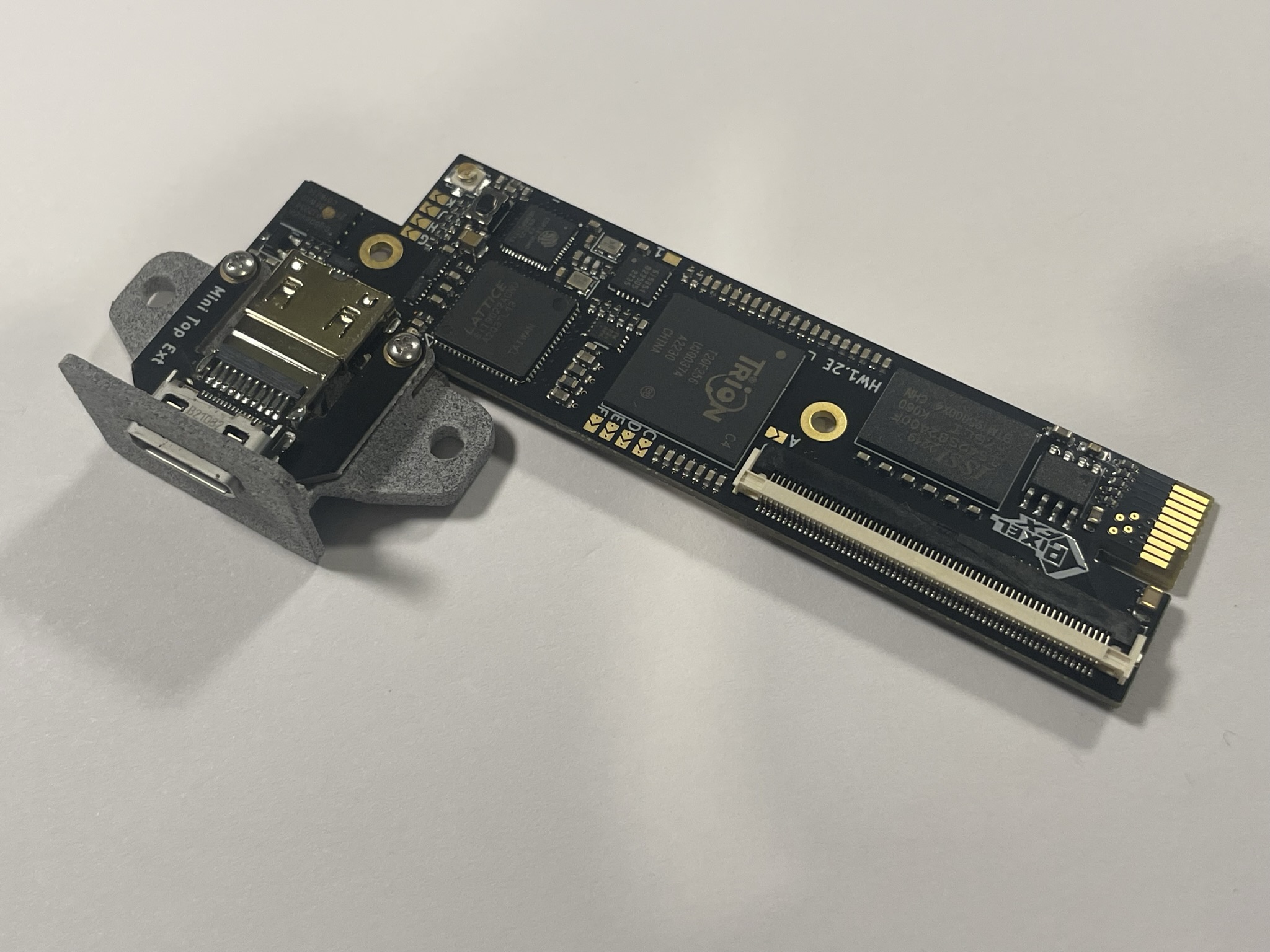
- PS1 Intermediate Board
- Mini HDMI Adapter
- Solder Lug
- Plastic Mount
- M2 4m Screw (1x)
- M1.6 Screw (2x)
- M1.6 Nut (2x)
- 220uf tantalum capacitor (3x)
- 10uf tantalum capacitor
Items required
- Temperature Controlled Soldering Iron
- Leaded Solder
- Non Corrosive, No Clean Flux (Amtech 559 / Kester 959T)
- 99% Isopropyl Alcohol
- Multi Meter
- Solder Braid / Desolerding Tools
- Small screw phillips screw drivers
- (3x) 0603 100-1K Ohm Resistors (Analog audio support only)
- Kapton tape or UV Solvermask
Step 0 - Clock Control and GEM Jumpers and Audio Resistors.
The Retro GEM PS1 can either run from the original console clock or use a generated clock that is identical to the consoles. Using the generated clock allows the console to run both PAL and NTSC frequencies. It is difficult to remove (required for clock mod) a resistor once the main flex has been installed. The installation steps assume you want to do the clock mod as it is recommened.
If you do not want to do the clock mod
- Do NOT remove the resistor from the PS1 main board. (Step 1 on main board prep)
- Do NOT close Jumper A on the Retro GEM.
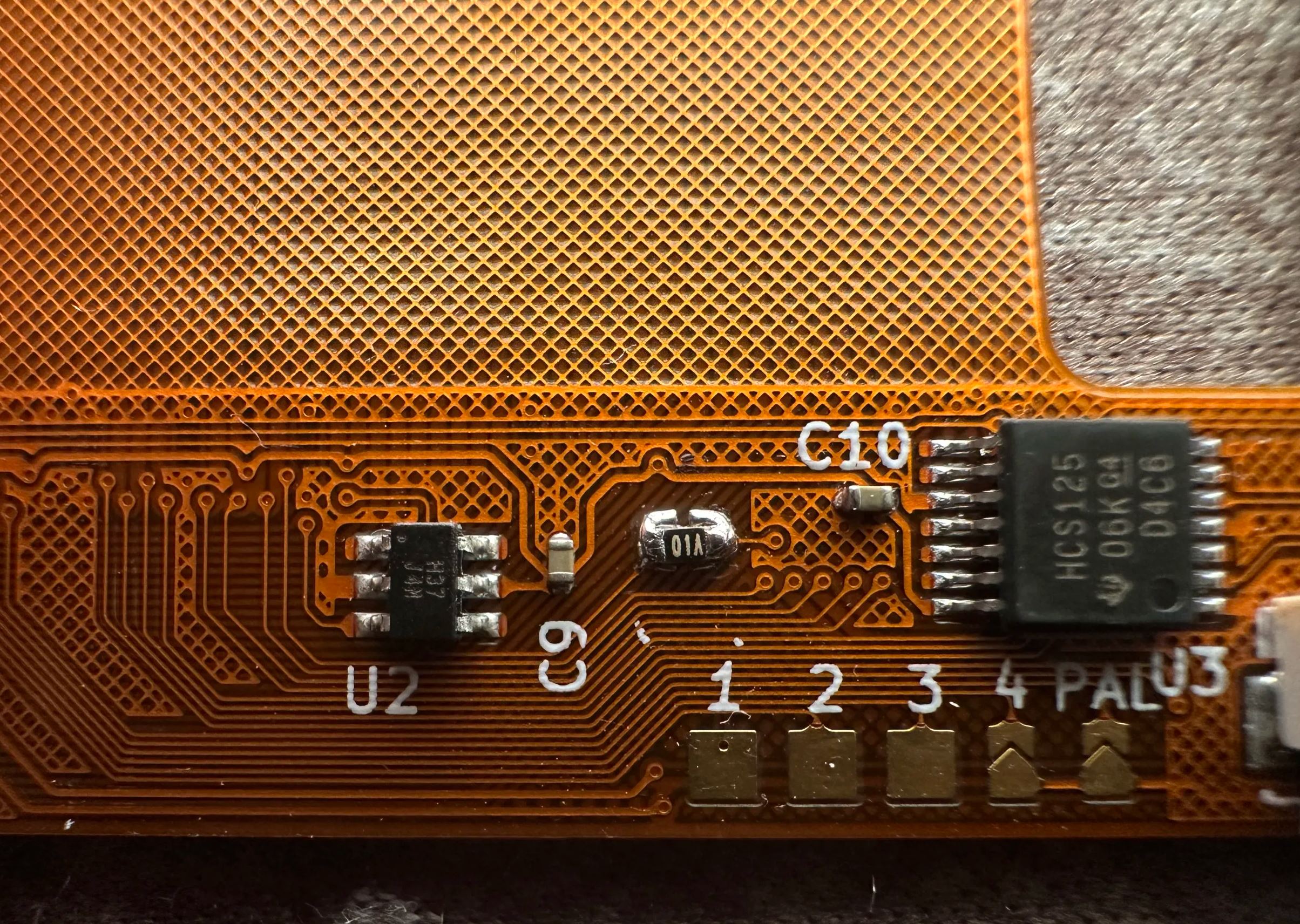
- Do NOT close the CLK jumper on the intermedate board.
Set the Retro GEM jumpers using this page:
https://docs.pixelfx.co/fxdigital-config.html
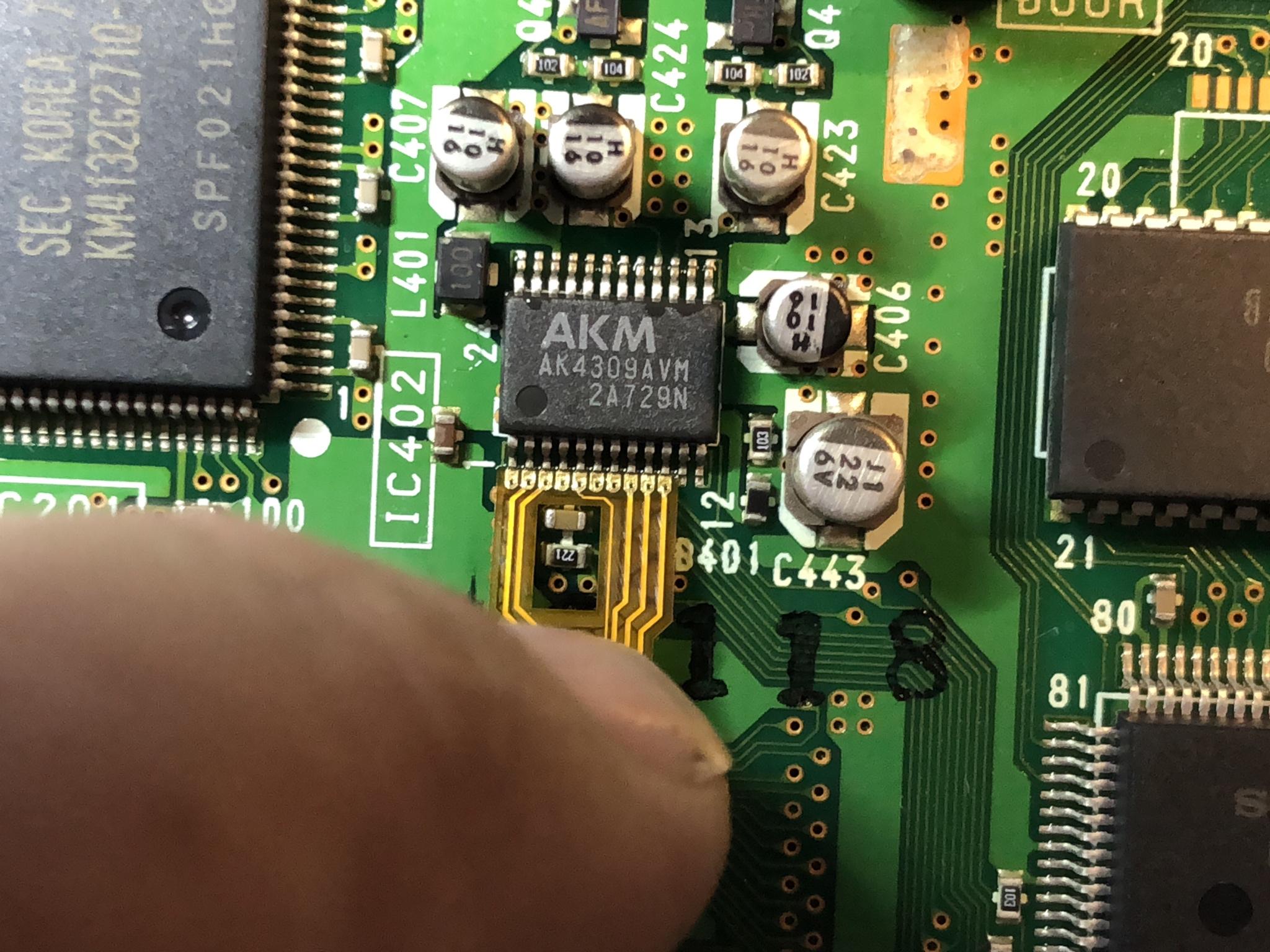
Only the analog audio may have some pops or crackles when the GEM is installed. This is caused by a high value series resistors. It is recommend you replace or install a resistor over the top of the existing resistor (Remember resistors in parallel reduce the the overall resistance)
There are three resistors that need changed as circled below: If the value of the resistor you have is 100-560 Ohm then you will want to remove the existing resistor and replace. If your resistor value is 560-1K ohm, this you should install the resistor over the top of the existing resistors.

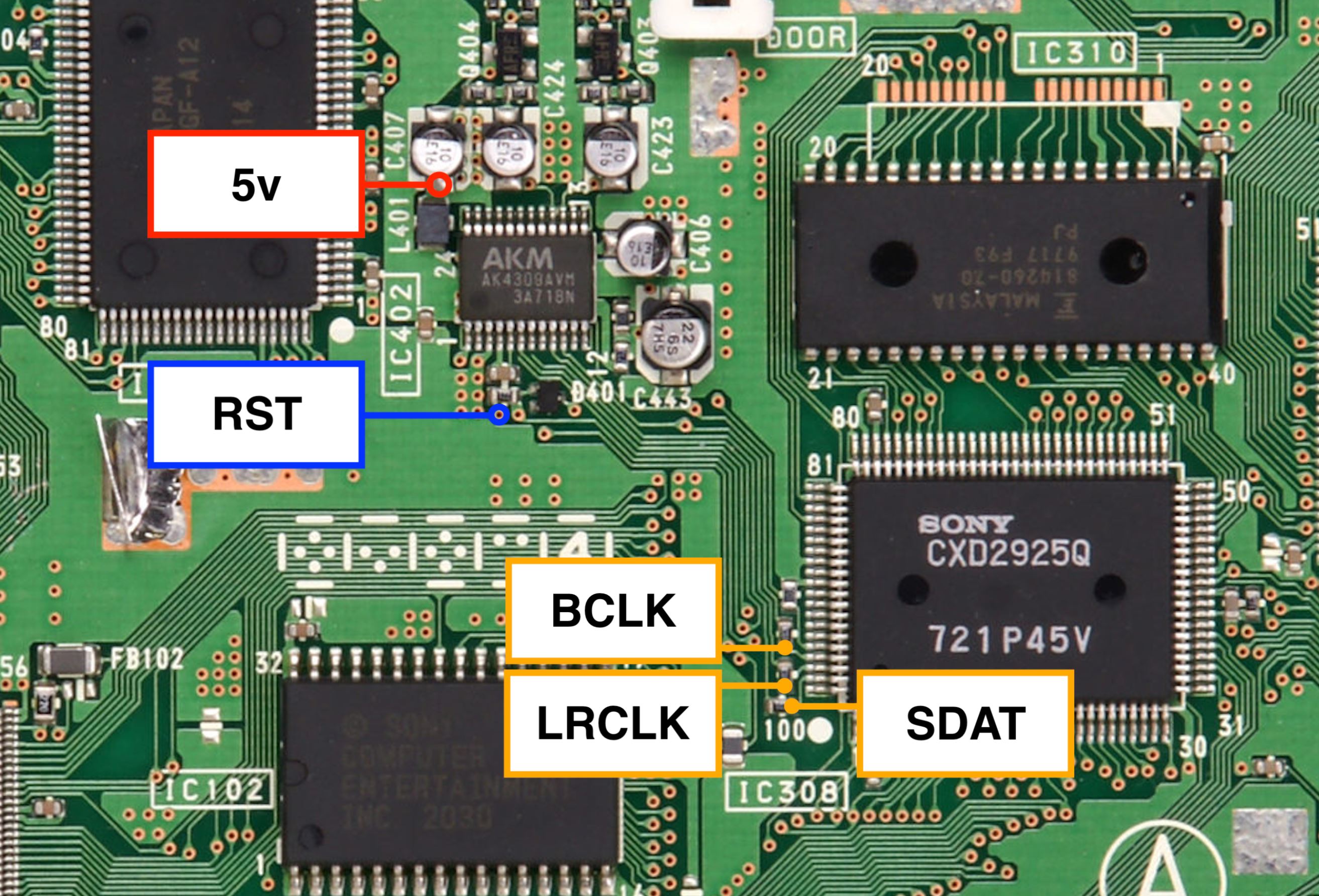
If you have a damaged audio flex or do not have resistors that you can repalce. You can alternativly omit the audio flex and run wires to directly hook it up. This is described below in the image, you must also wire up RST and 5v as these signals go over the audio flex.
Read More
Step 1 - Motherboard Prep
Click to expand/collapse
Remove the metal shield that is soldered to the PS1 Motherboard. This will not be used and can be tossed. An easy way to remove is to just cut the legs off.

Remove the serial port. Use hot air / quick chip / desoldering braid / Desoldering gun etc.

Select your model:
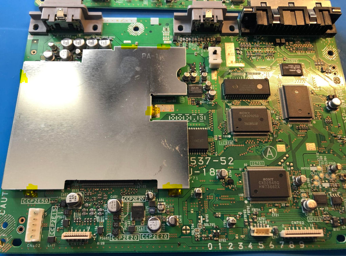
PU-18
Remove the 5 components highlighted in yellow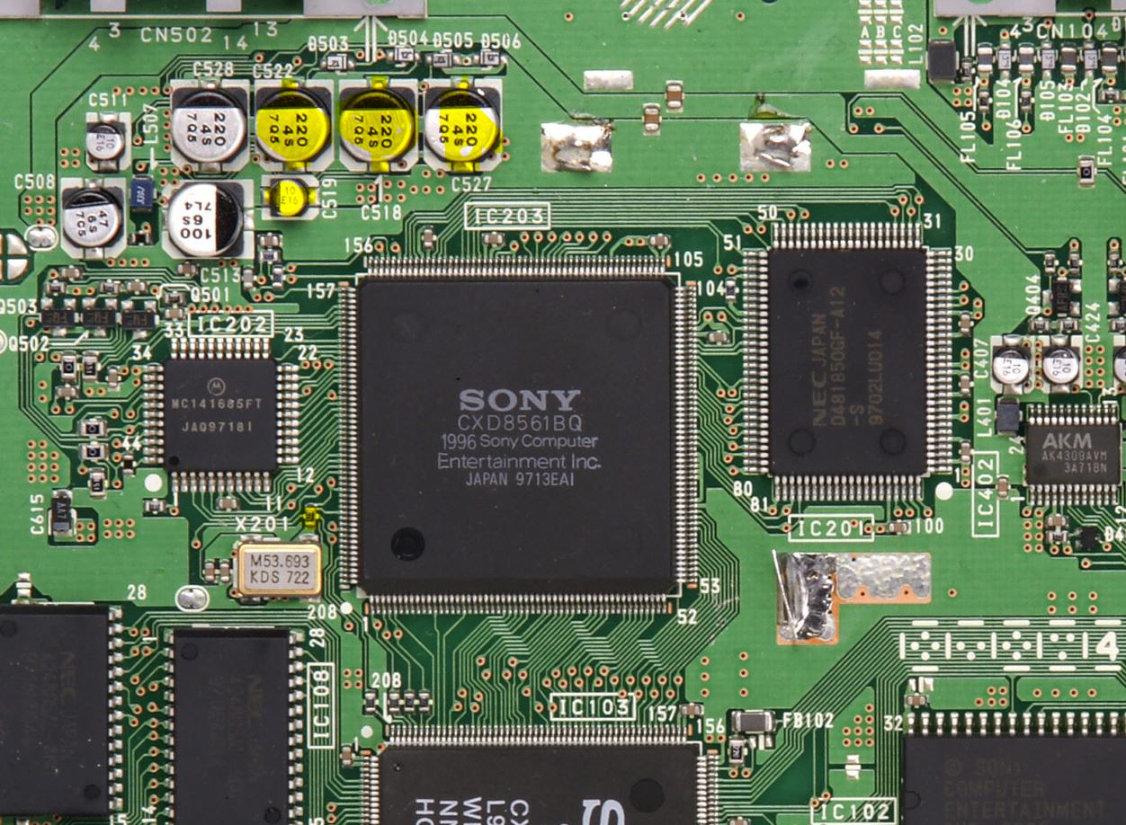
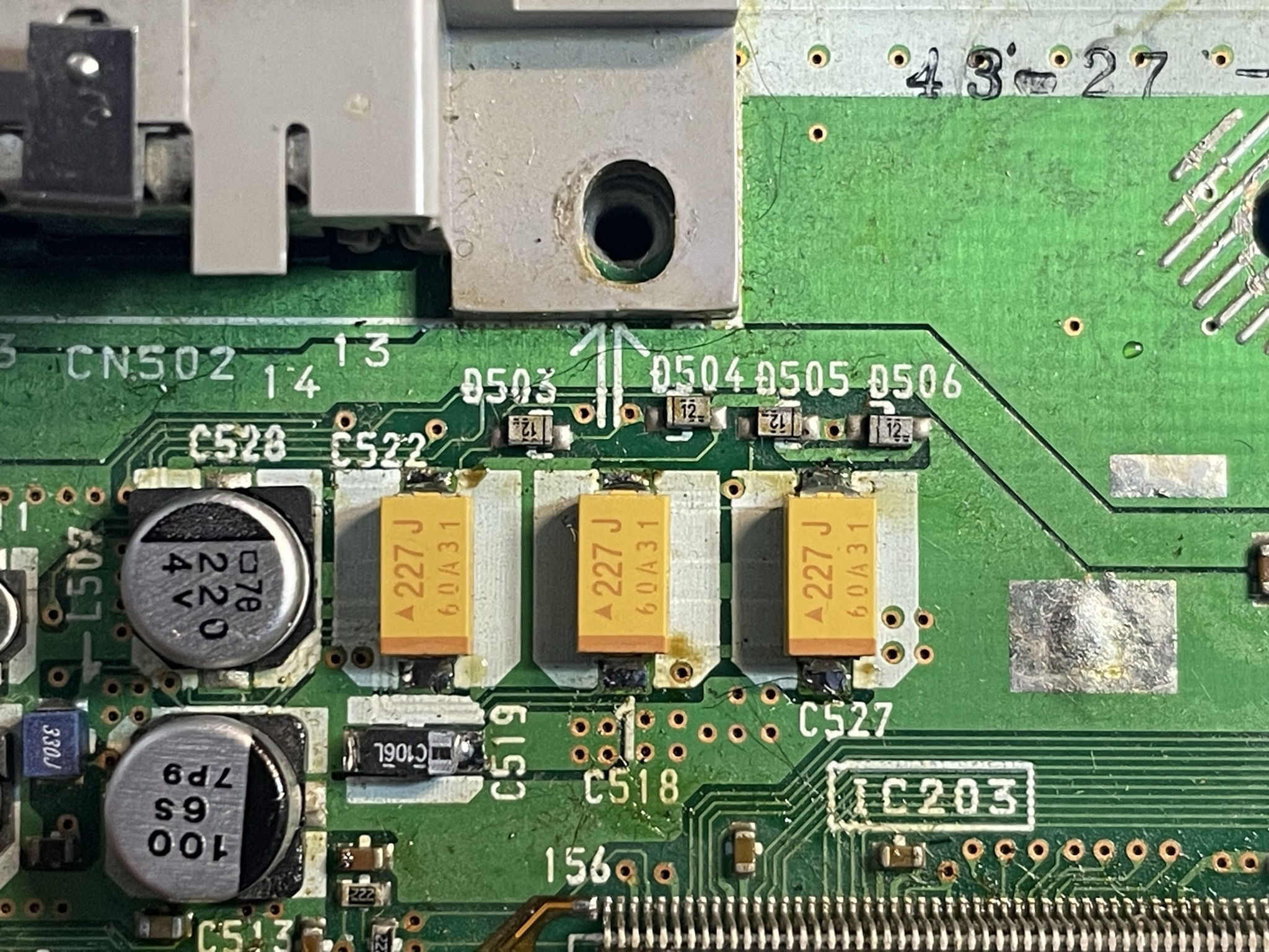
Install the 3 220uf tantalum capacitor and the 1 10uf tantalum capacitor. Pay close attention to the orientation in the picture below.
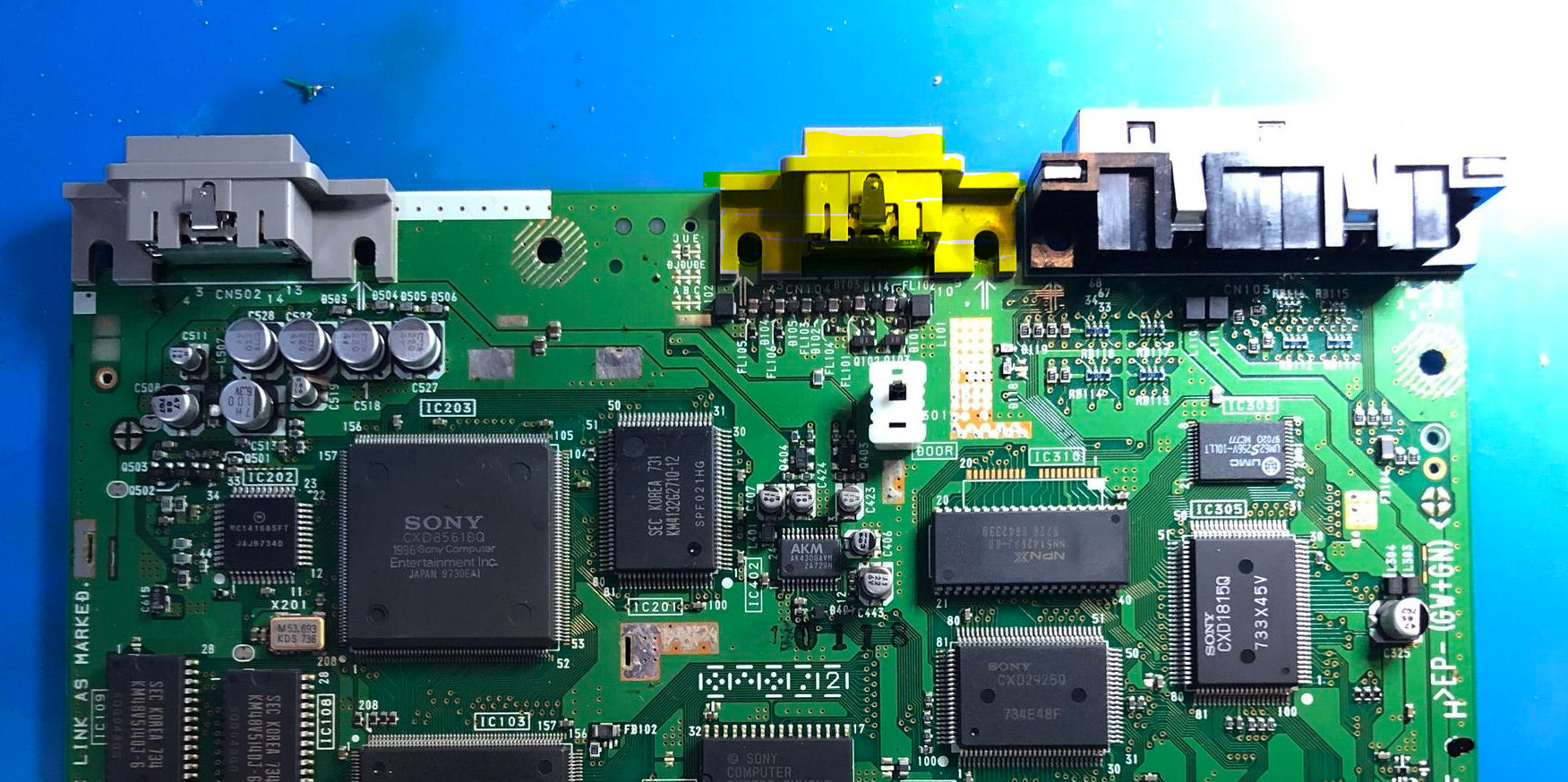
PU-20
Remove the 7 components highlighted in yellow
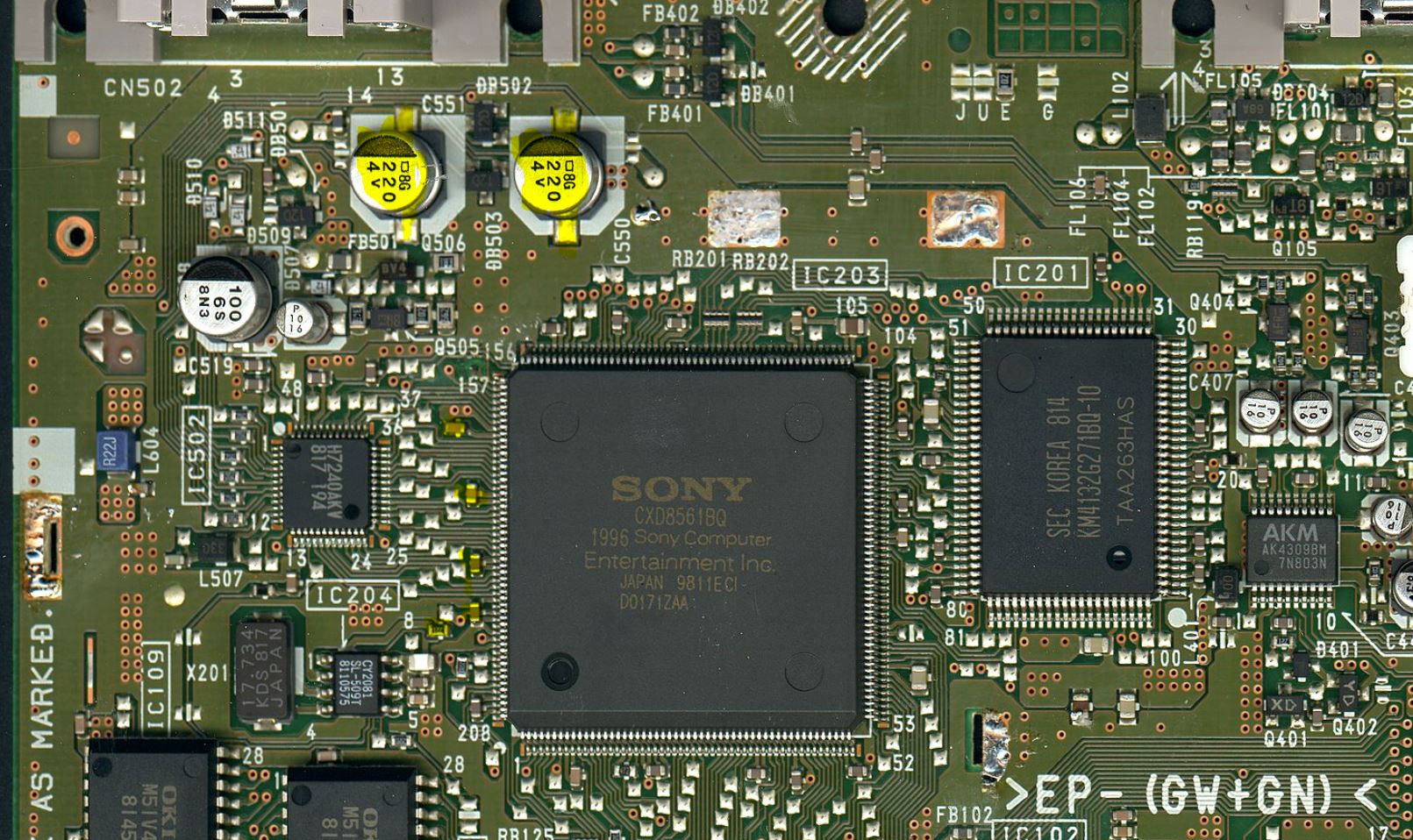
Install the 2 220uf tantalum capacitors. Pay close attention to the orientation in the picture below.

Step 2 - Installing the flexes
Click to expand/collapse
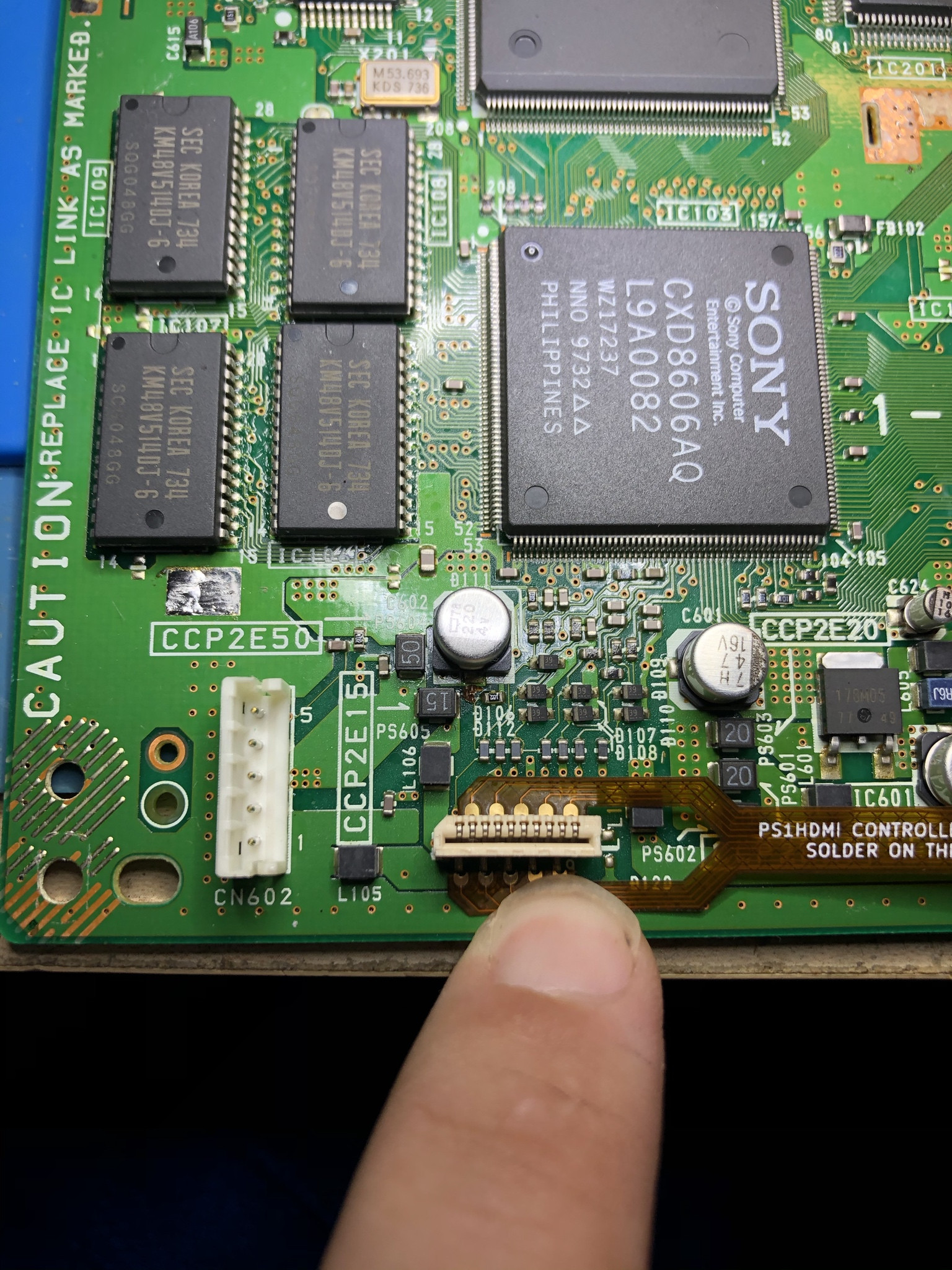
Install the Controller Flex:

Install the Audio Flex (Your audio IC might have 2 less pins, this is fine):

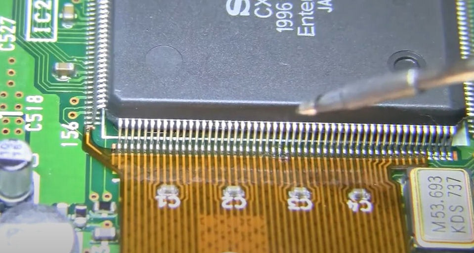
Before installing the main flex, cover up any exposed vias that make come into contact with the flex. The CLK_EN pin can come into contact with via that is going to ground. Make sure you cover this up.
Install the main flex. I do not recommened drag soldering on this as its easy to move pins and bridge.

Step 3 - Installing the GEM
Click to expand/collapse
Insert the nuts into the plastic holder
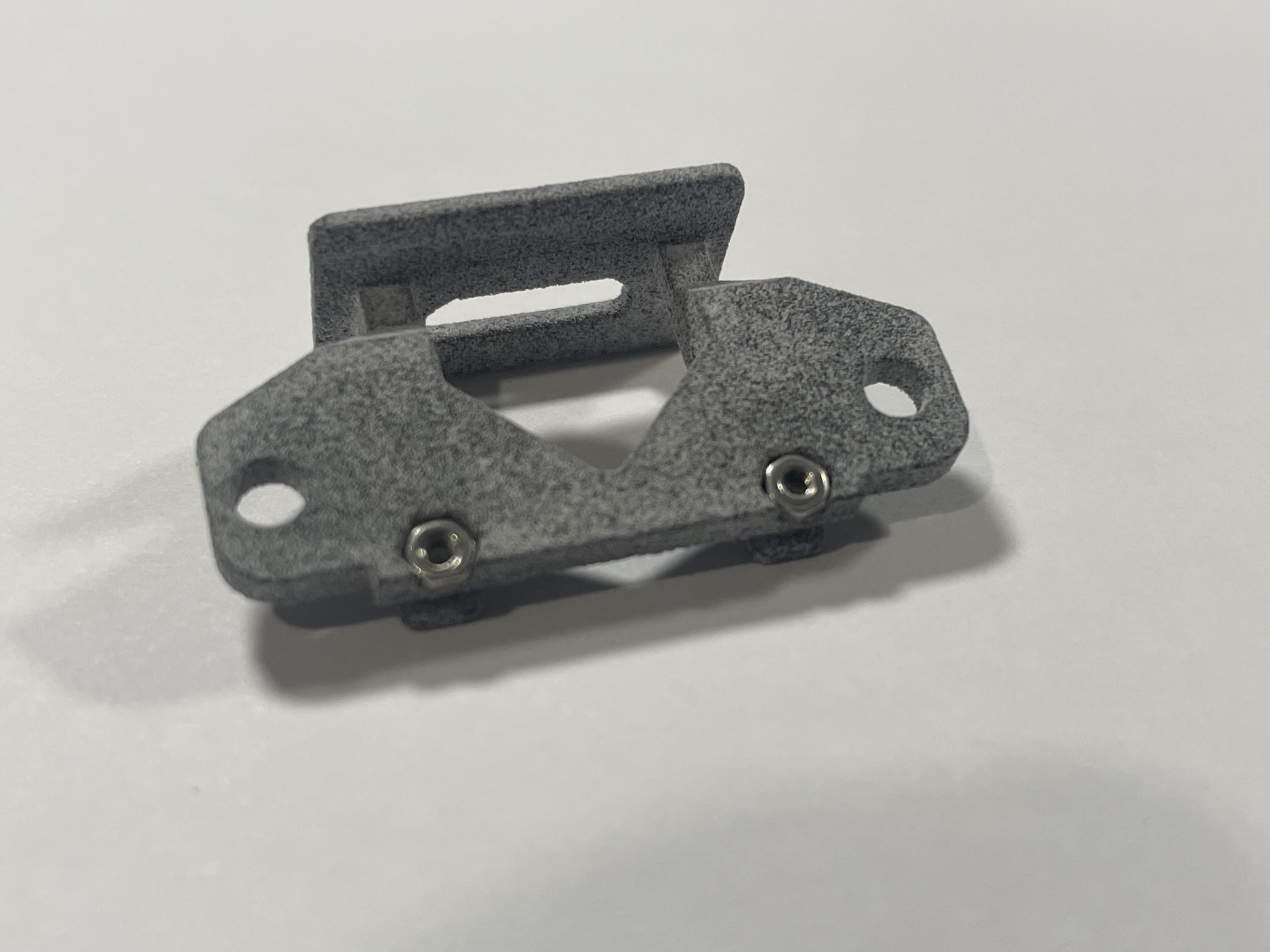
Insert the male hdmi adapter and slide the plastic holder together with the GEM together. Secure with the M1.6 screws. Do not overtighten.
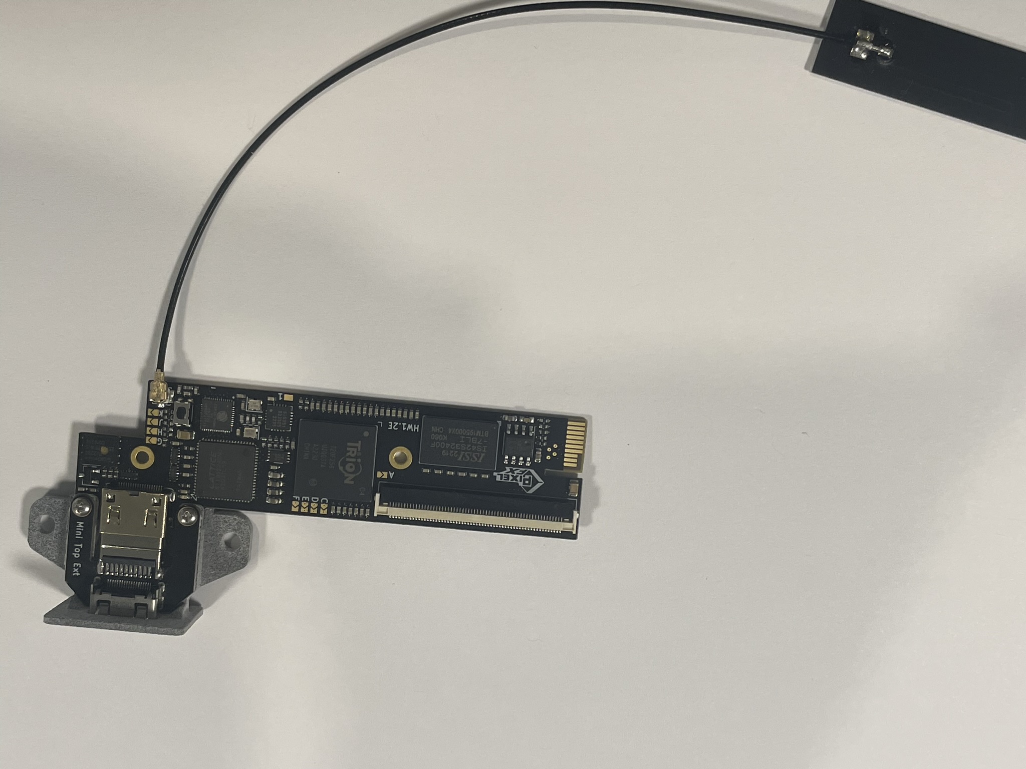
Plug in the IPEX antenna.
Step 4 - Installing the intermediate board.
Click to expand/collapse
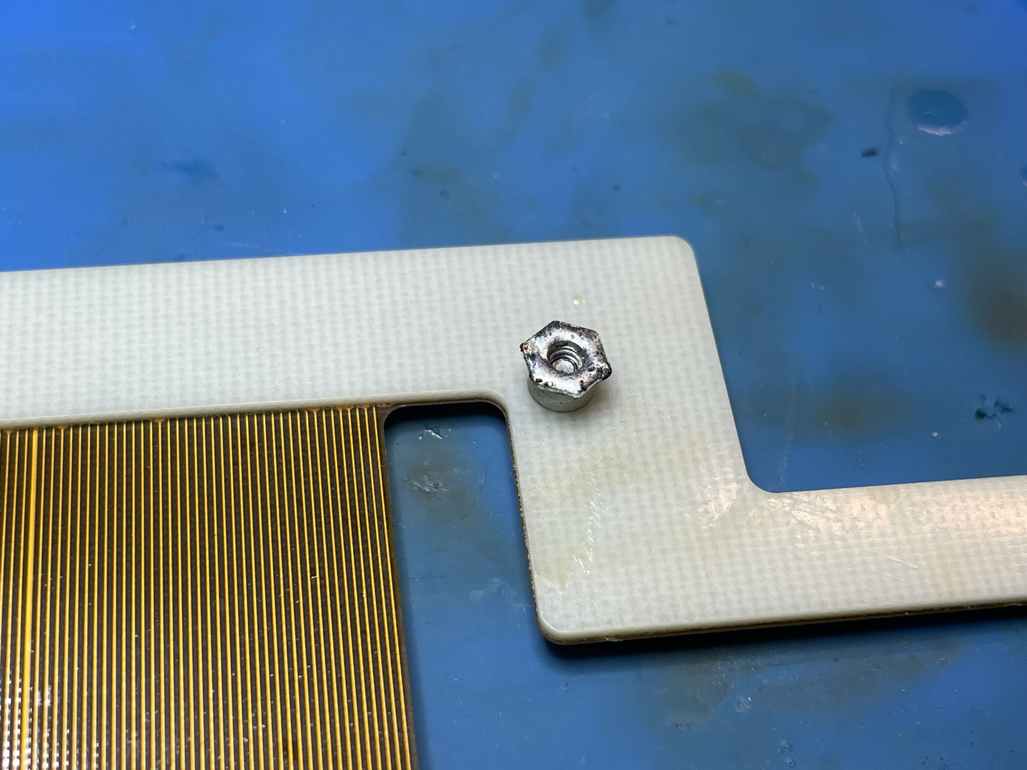
Screw the solder lug into place on the intermediate board.
Apply a small amount of solder to the bottom of the lug. Do not solder the screw to the lug. You must be able to unscrew it.
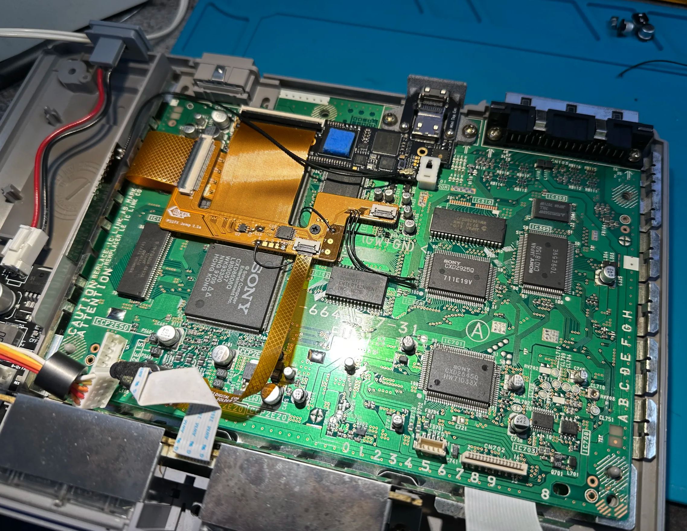
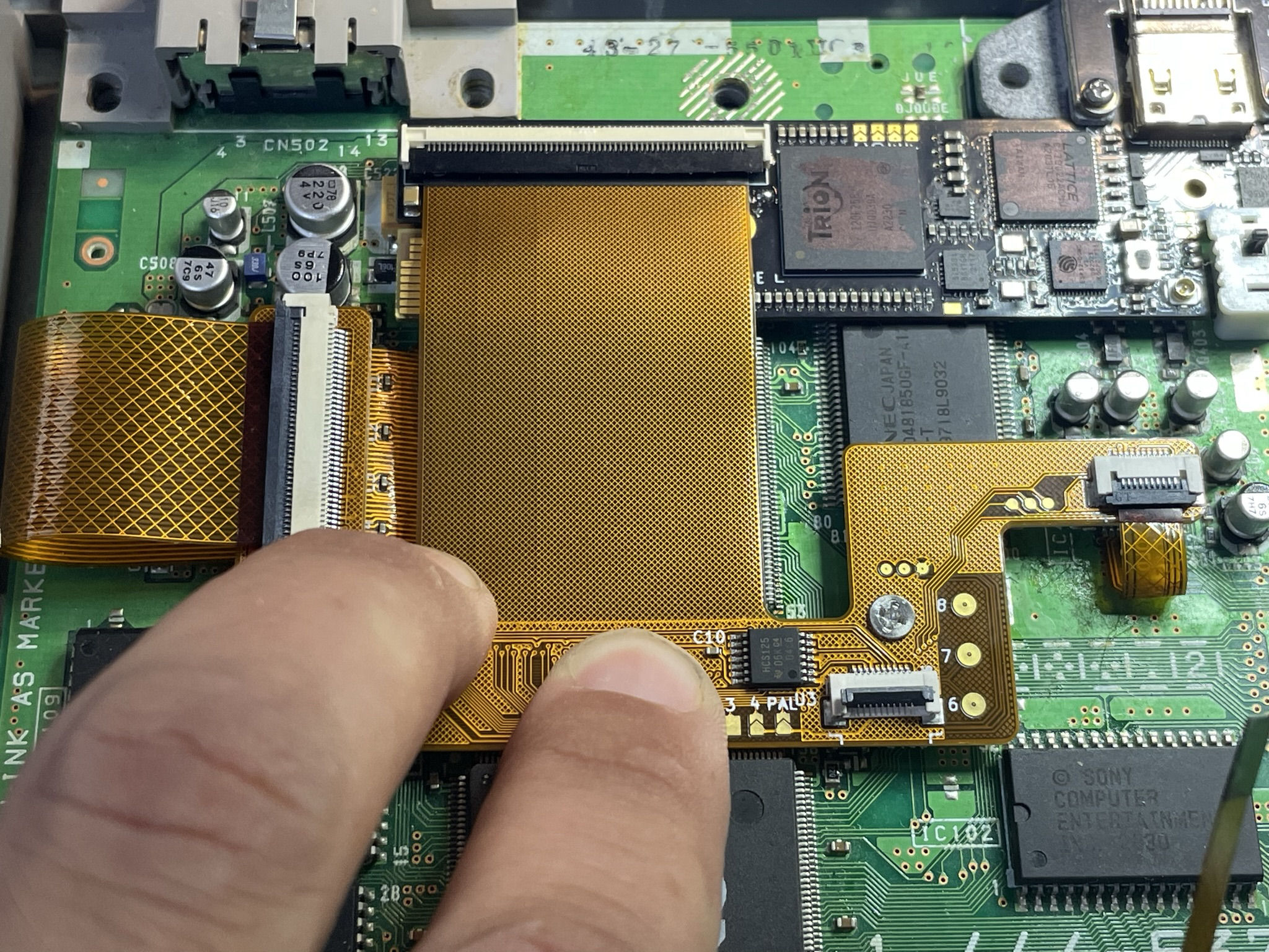
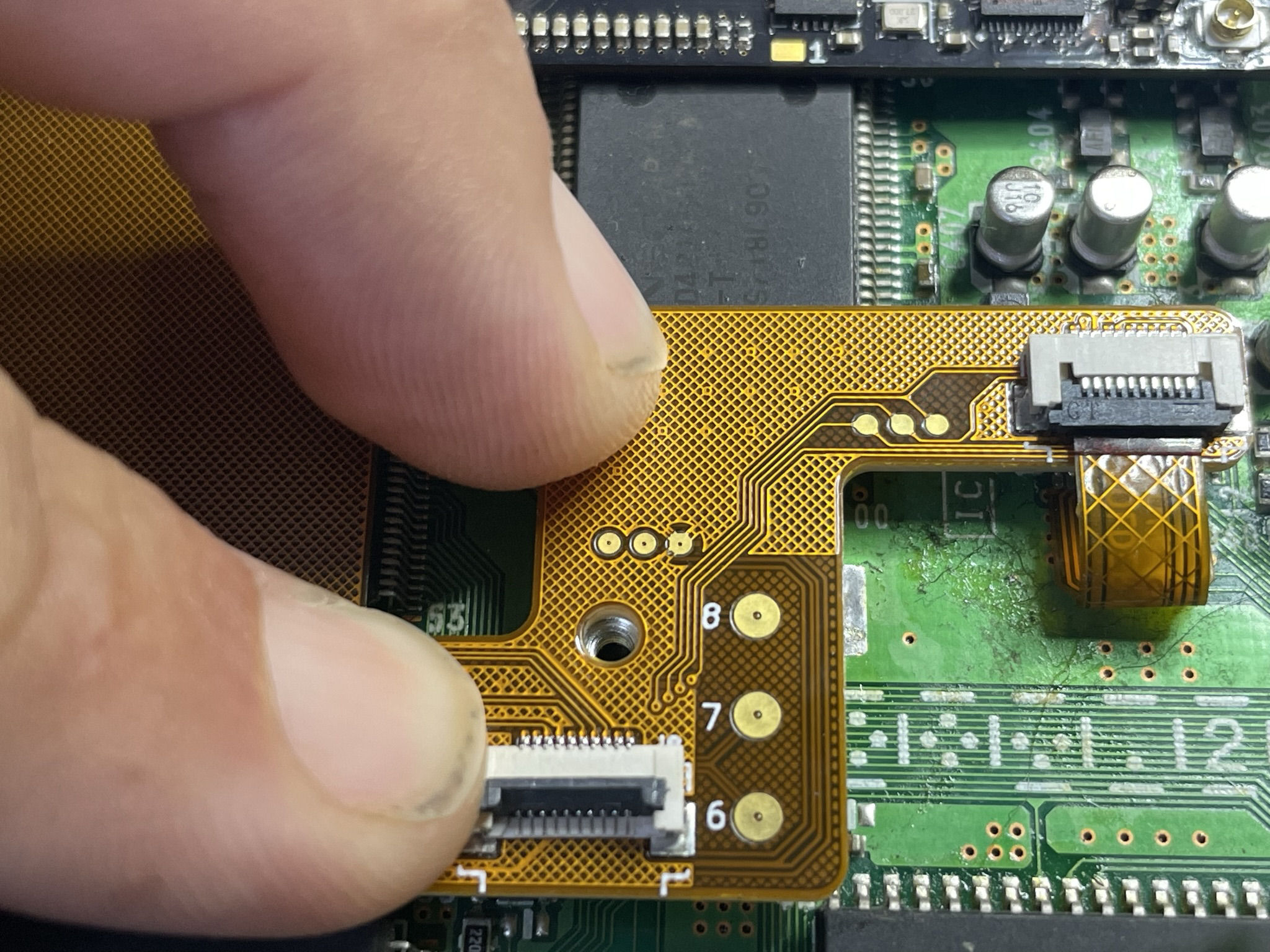
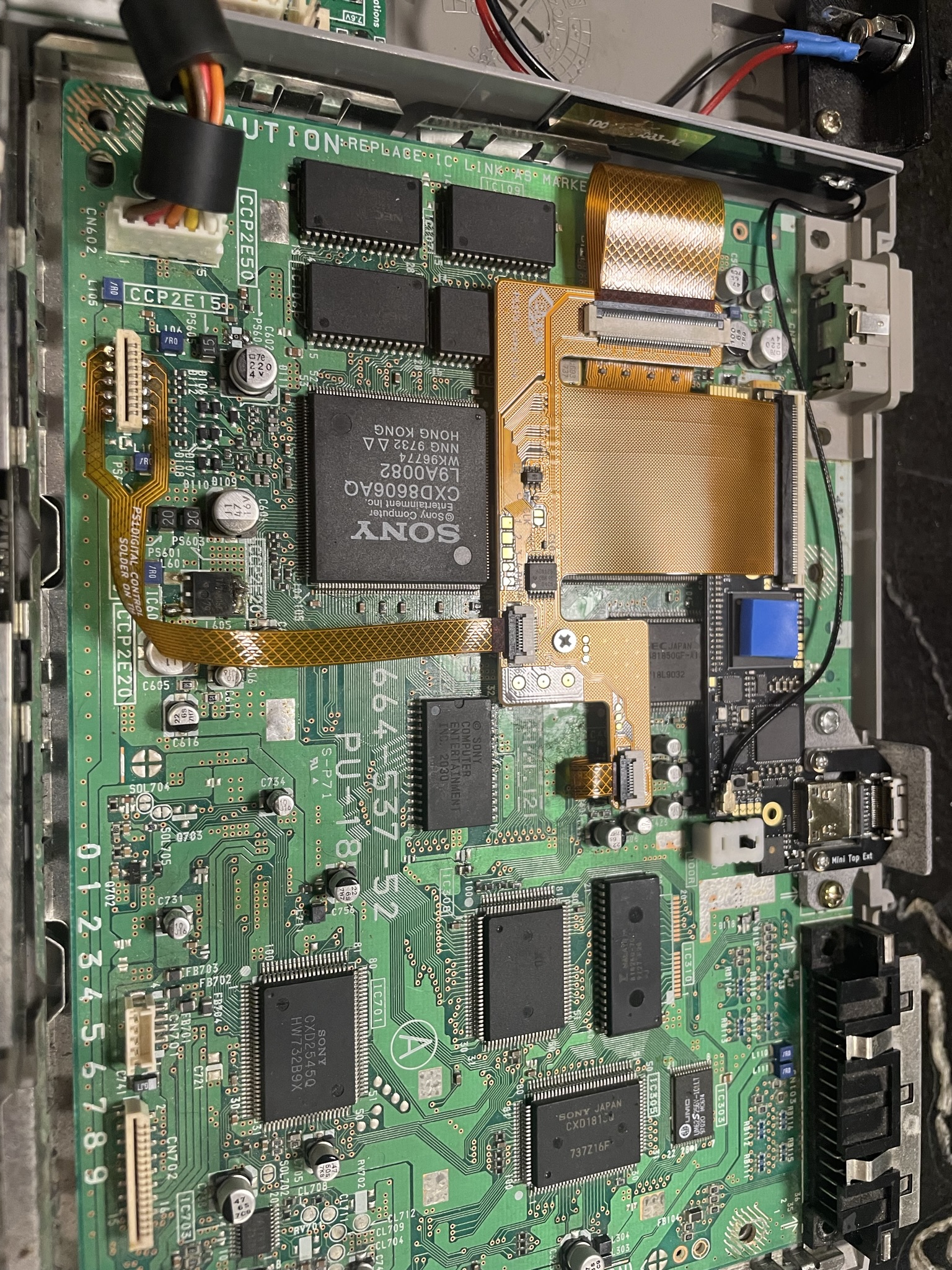
Install the Retro GEM with the OEM screws and Connect all the FFC cables exepect the controller. This is the placement of the intermediate board.
While holding down the intermediate board with your hand, remove the screw from the solder lug and unplug all flexes. Carefully remove the intermediate board while all the same time not moving the solder lug.
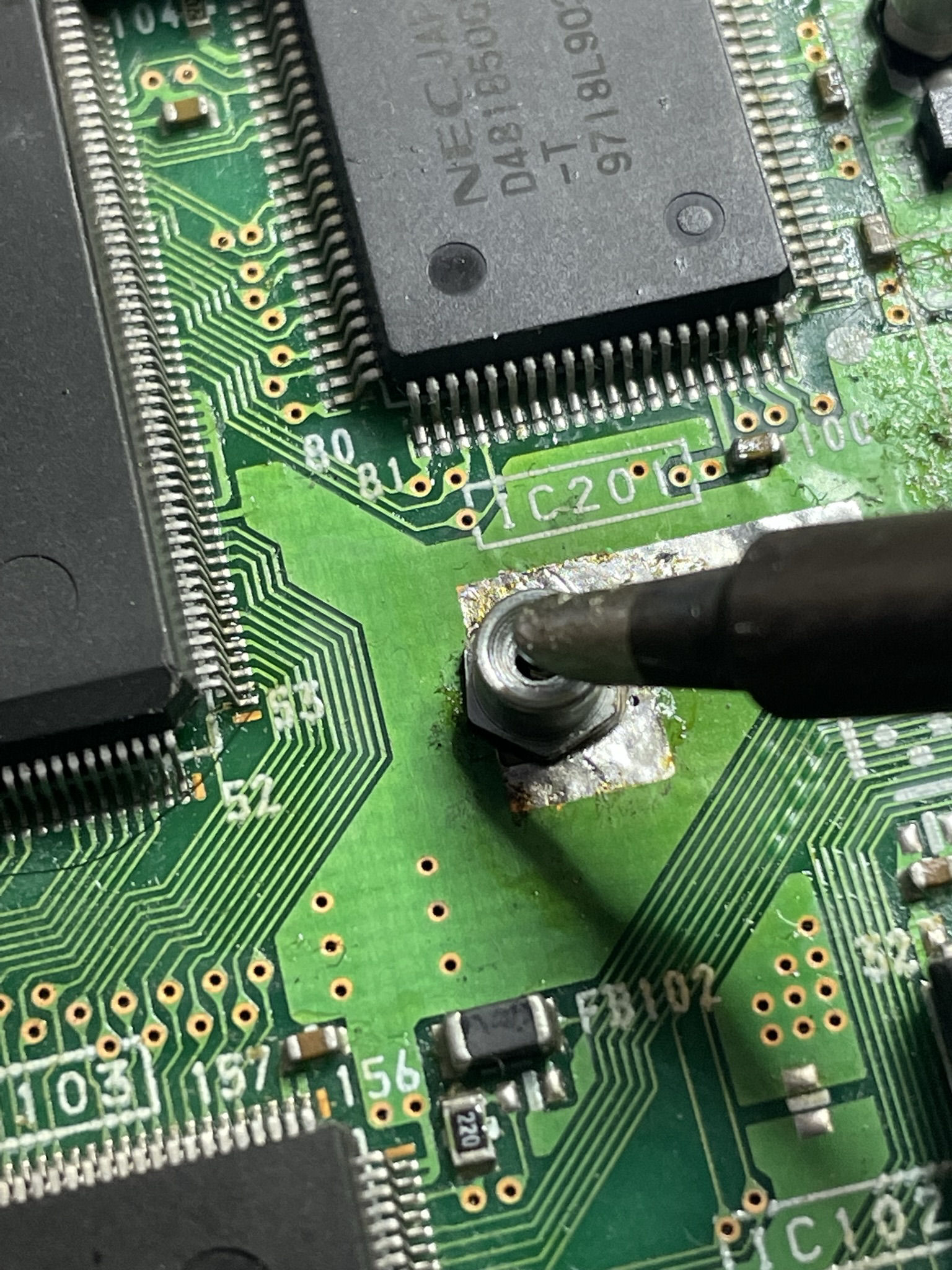
Hold the solder lug with tweezers and apply heat to the top of the lug. This solder you applied earlier will melt and fuse the lug to the main board. Feel free to add more solder if needed. Just make sure the placement does not move.
Install the intermediate flex back on and plug in all flex cables.
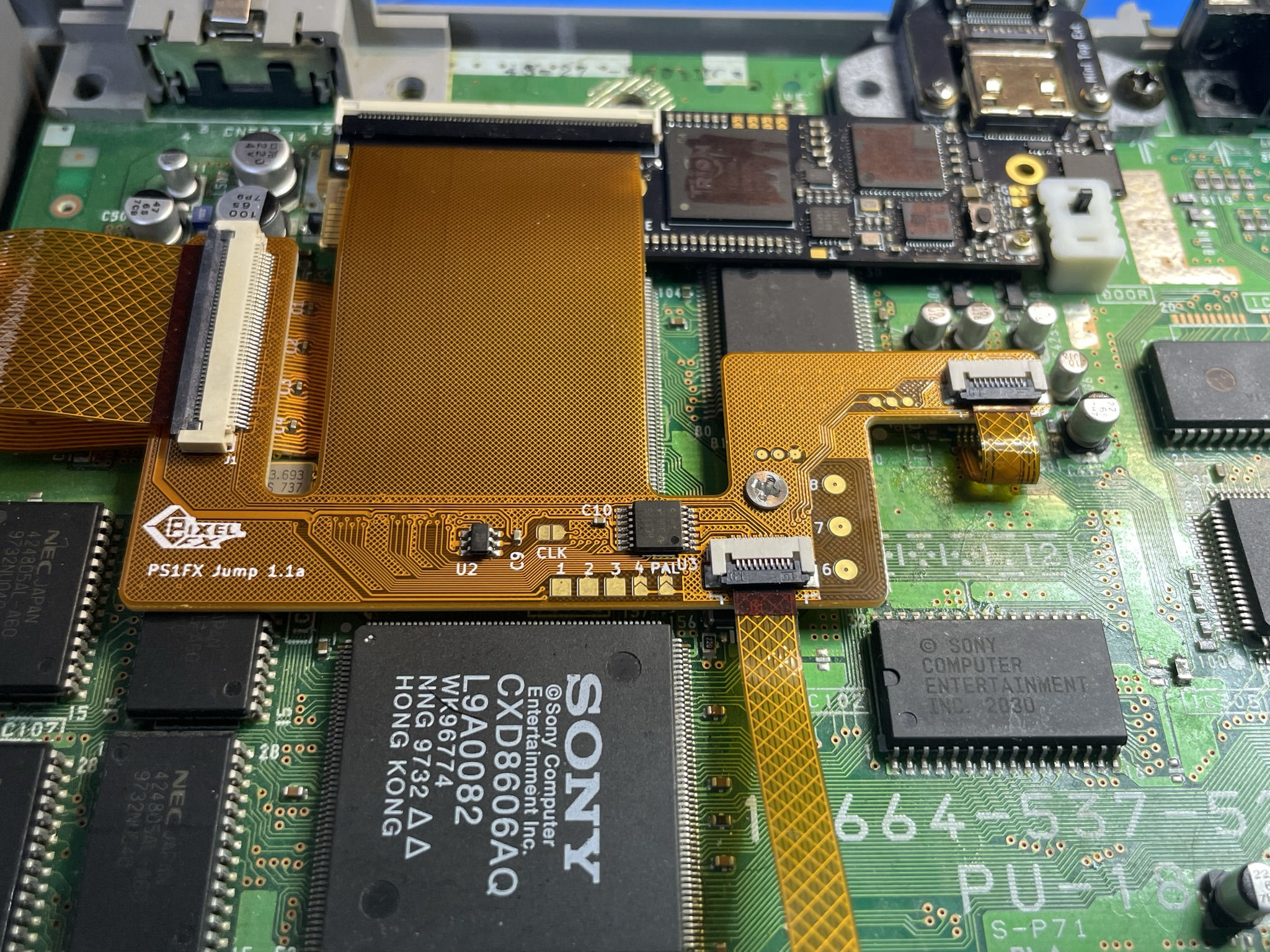
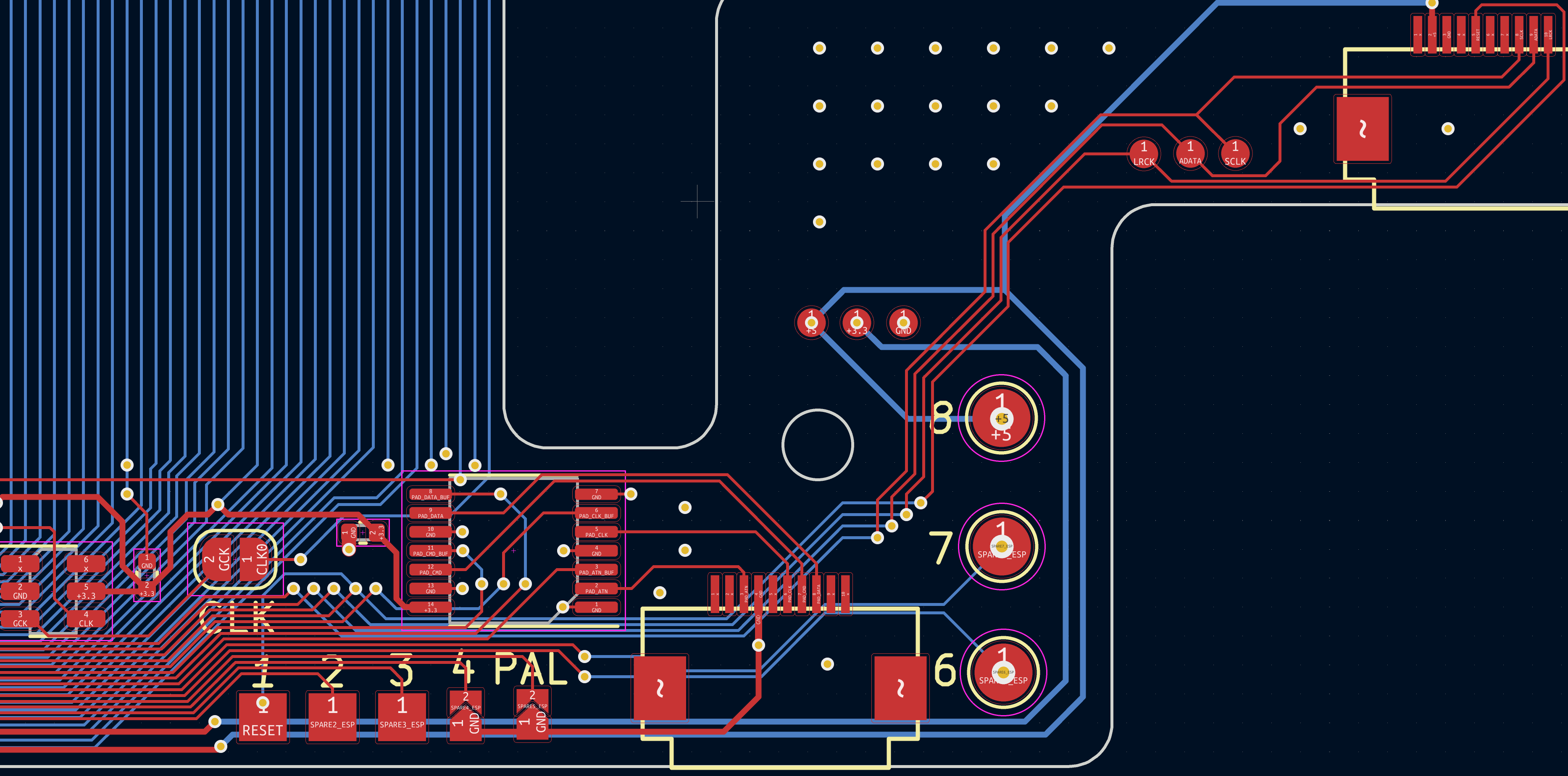
If you have a PAL console please close the PAL jumper found on the intermediate board.
Close the CLK jumper on the intermedate board if you chose to do the clock mod.
Some Models might require a 100 ohm resistor to be use across the clk jumper, Only install if your video has glitchyness not due to soldering issues
Step 5 - Testing the installation
Click to expand/collapse
Now that everything is connected you should test the installation to make sure everything works as expected.
IF YOU ARE USING AN X-STATION it must be connected and hooked up, otherwise you will get a black screen.
Verify you have no DIRECT shorts on the 3.3V to GND and 5V to GND. If you have a direct short and power on you will blow fuses on the PS1 that will have to be replaced.
 MISSING
If no shorts are found do a quick power test. And verify you get video via the HDMI, if you do not go back and verify the installation of the main flex and audio flex.
Confirm audio works and also the controller OSD by hitting L1 + R1 + DPAD Right + Circle all at the same time.
Step 6 - Finishing up
Click to expand/collapse
Now is best time to wire in the lid switch for the x-staiton (This is totally optional). This is no required, but will allow the x-staiton to boot with the disc drive open.
For the lidwitch to be enabled make sure to set OSD->Main Menu->System->PS1Digital Settings->Extra Pins to Lidswitch
Pad 2 on the intermediate board is the input, and goes to the switch on the console
Pad 3 on the intermediate board is is the output. Goes to where the trace cut is preformed.

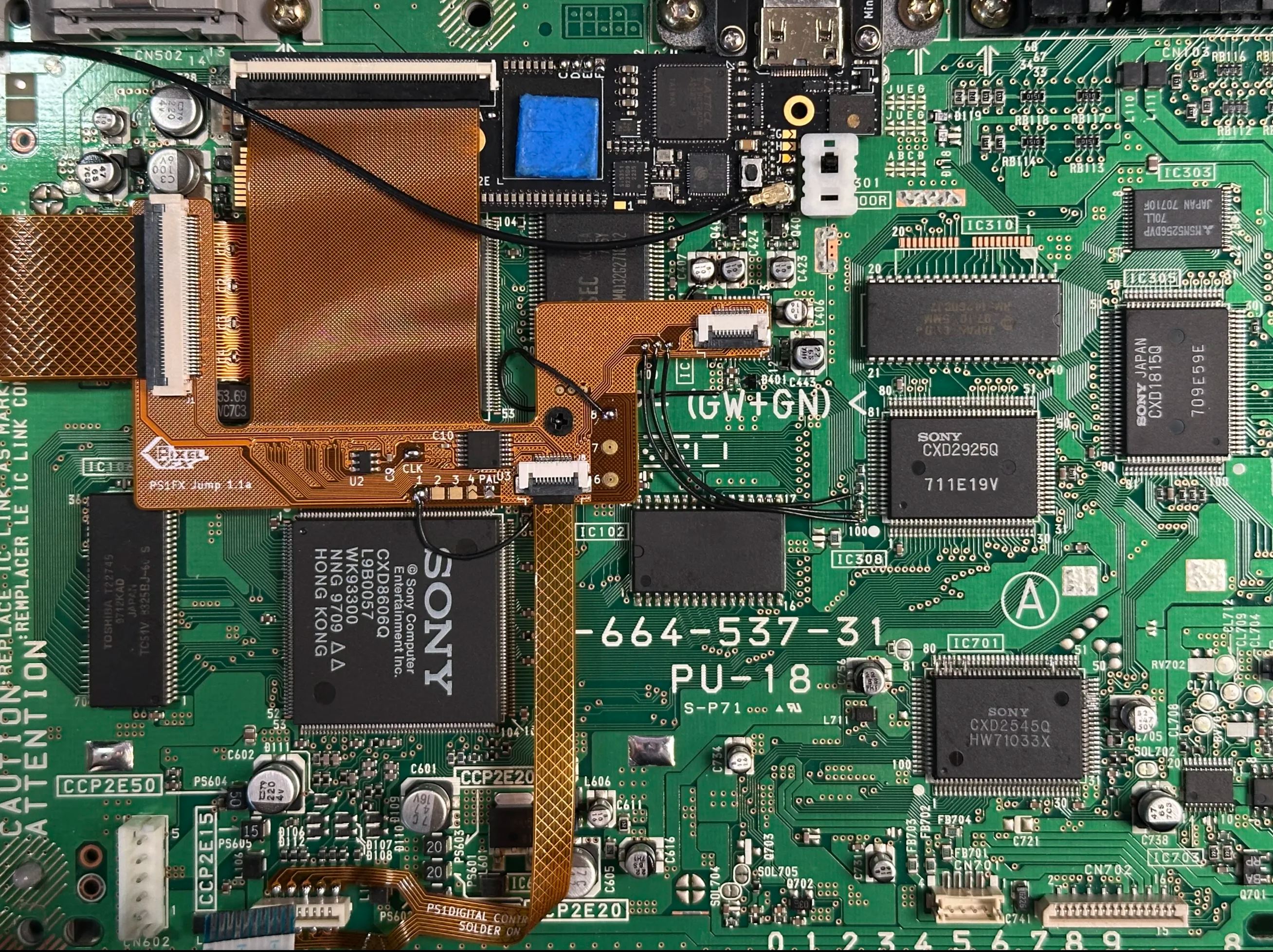
Once the installation is confirmed good, install the thermal pad on the FPGA and route the antenna as shown.
Congratulations! Enjoy the Retro GEM and we appreciate your support.