Retro GEM N64 Installation Instructions
Disclaimer: This kit is for advanced installers only. Install at your own risk. We cannot be held responsible for damage to your console and/or kit. Each kit is individually tested and confirmed working before being shipped.
Before you begin:
The kit is compatible with all N64 models/regions; with the exception of Pikachu models. (This requires special mounting not supplied from Pixel fx)
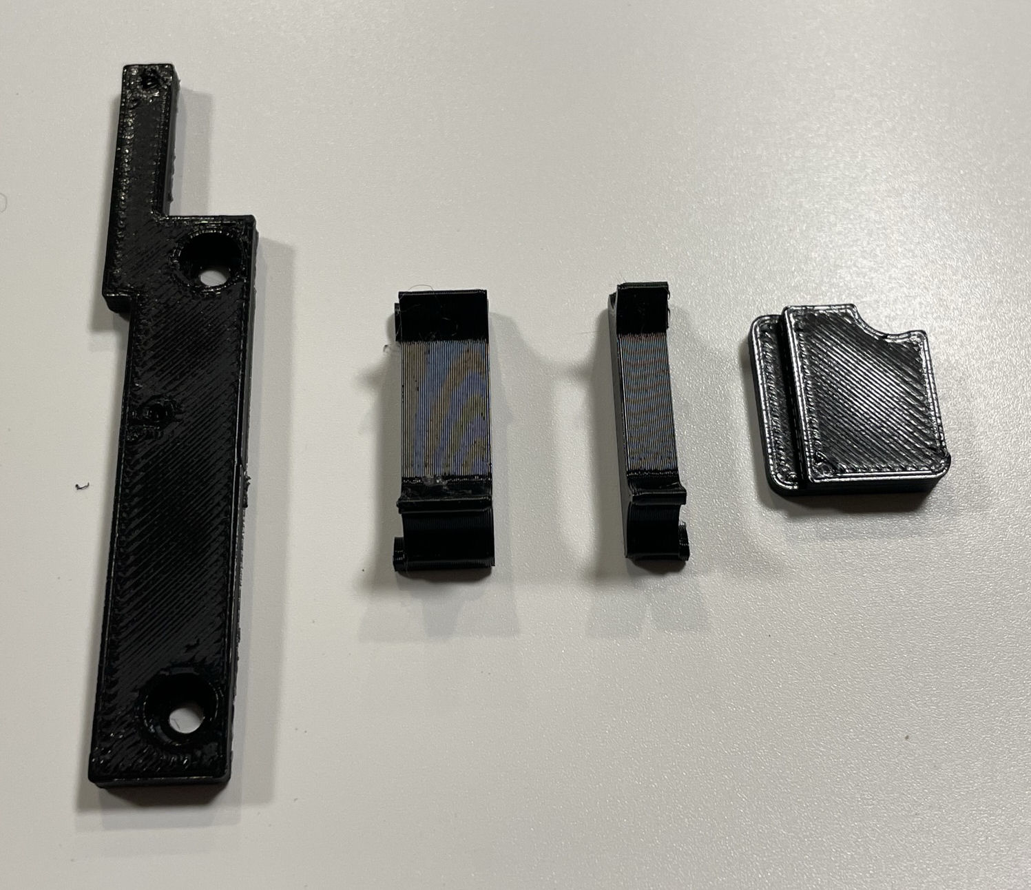
You will be required to preform a small case cut for the mini HDMI connector. There is a NO CUT option but these parts must be 3D printed and used during the installation:
These parts can also be purchased at: https://laserbear.net/products/n64-digital-no-cut-mod.
Please be aware that both Analog and HDMI cannot be used at the same time when using the no cut solution.
Kits sold after April 1st 2025 will have a new mounting system for the HDMI and also utilize M2 inserts.
Kit includes:
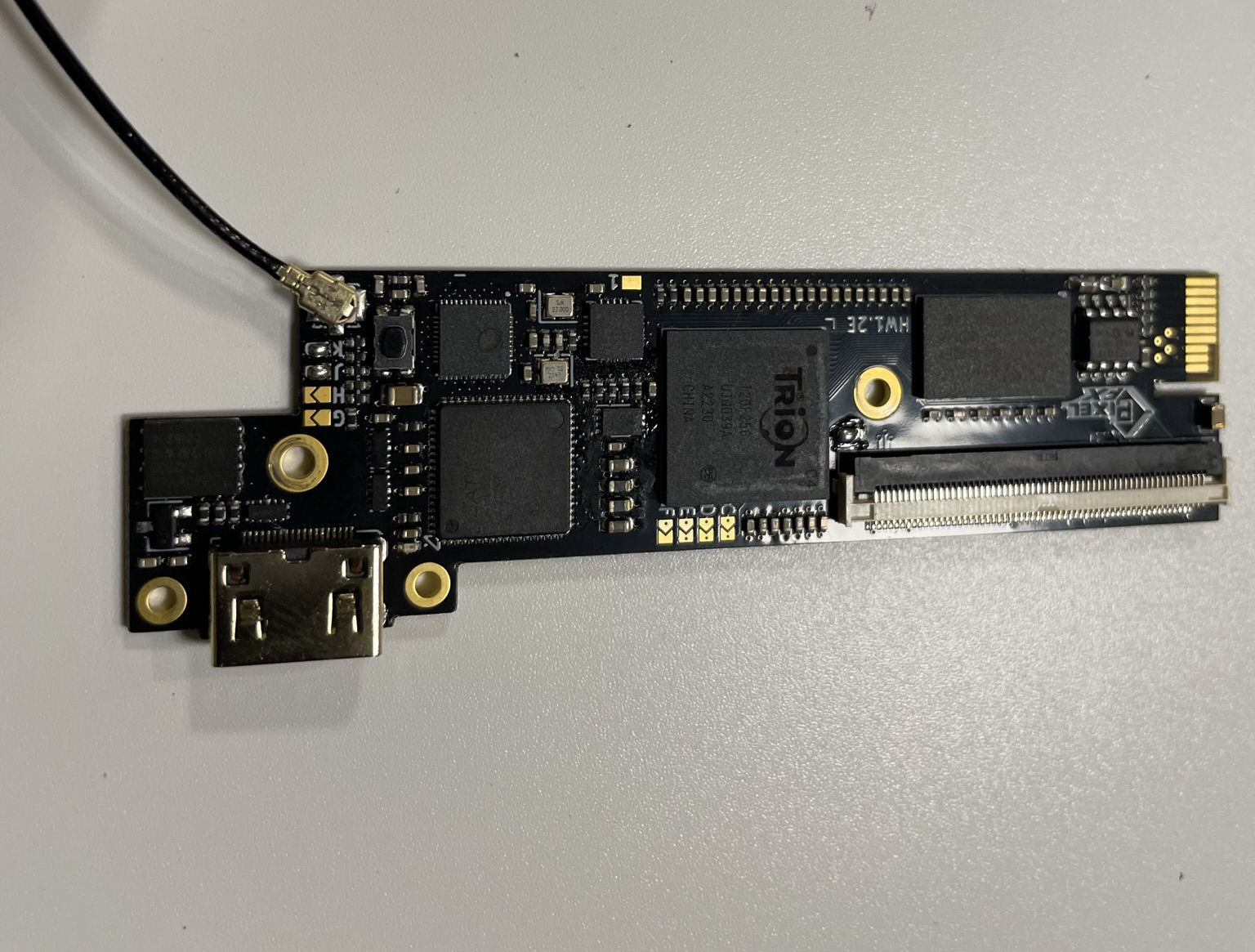
- N64 Main Flex
- N64 HDMI Board / SQ Mini HDMI board (The latter is kits sold after 4/1/25)
- Male HDMI Adapter
- 150mm 18p FFC Cable
- Plastic Panel block
- M2 Nuts (2x) / M2 inserts (2) (The latter is kits sold after 4/1/25)
- M2 4mm Screw (2x)
Items required
- Temperature Controlled Soldering Iron
- Leaded Solder
- Non Corrosive, No Clean Flux (Amtech 559 / Kester 959T)
- 99% Isopropyl Alcohol
- Multi Meter
- Miniature File Set & Exacto Knife (Cut Version)
- Kapton Tape
- 30 AWG wire
- 4.5mm Gamebit Adapter (N64 Teardown)
- Small screw phillips screw drivers
Step 0 - Clock Control and GEM Jumpers.
The Retro GEM N64 can either run from the original console clock or use a generated clock that is identical to the consoles. Using the generated clock allows the console to run both PAL and NTSC frequencies. There are some restrictions with the clock mod. Composite and S-video will be out of phase with the generted clock and jailbars can be present these outputs. Some N64s also do not work well with the clock mod (Sync drops), particulary PAL consoles. A resistor is needed for these consoles that do not work well. With these caveats its not recommened to do the clock mod unless you need the DFO.
Set the Retro GEM jumpers using this page:
https://docs.pixelfx.co/fxdigital-config.html
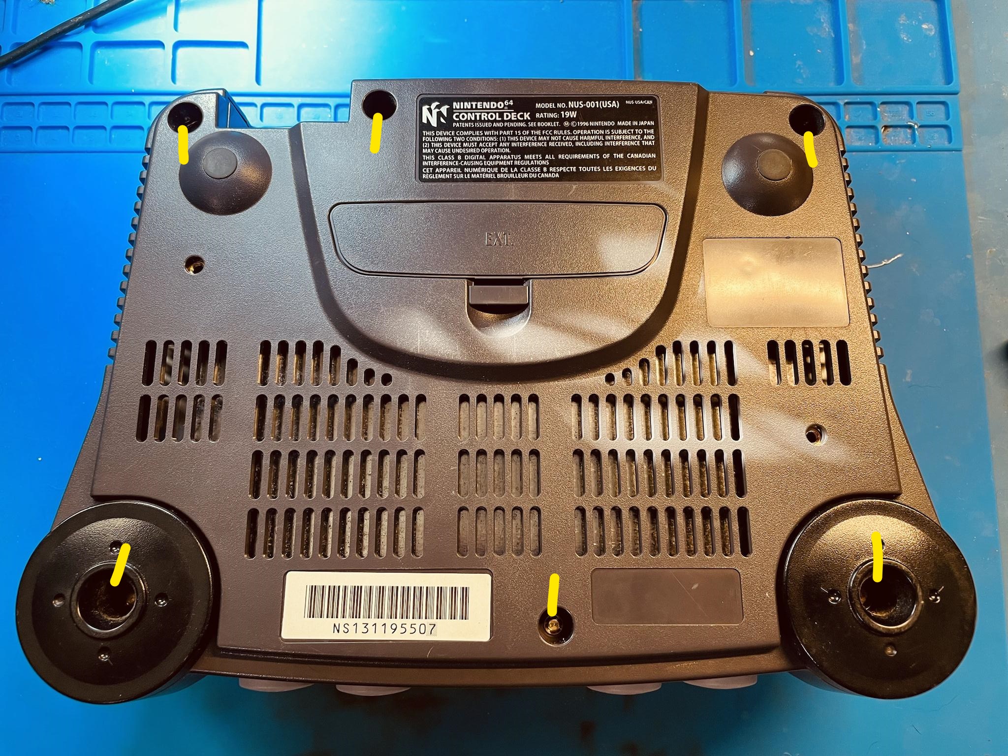
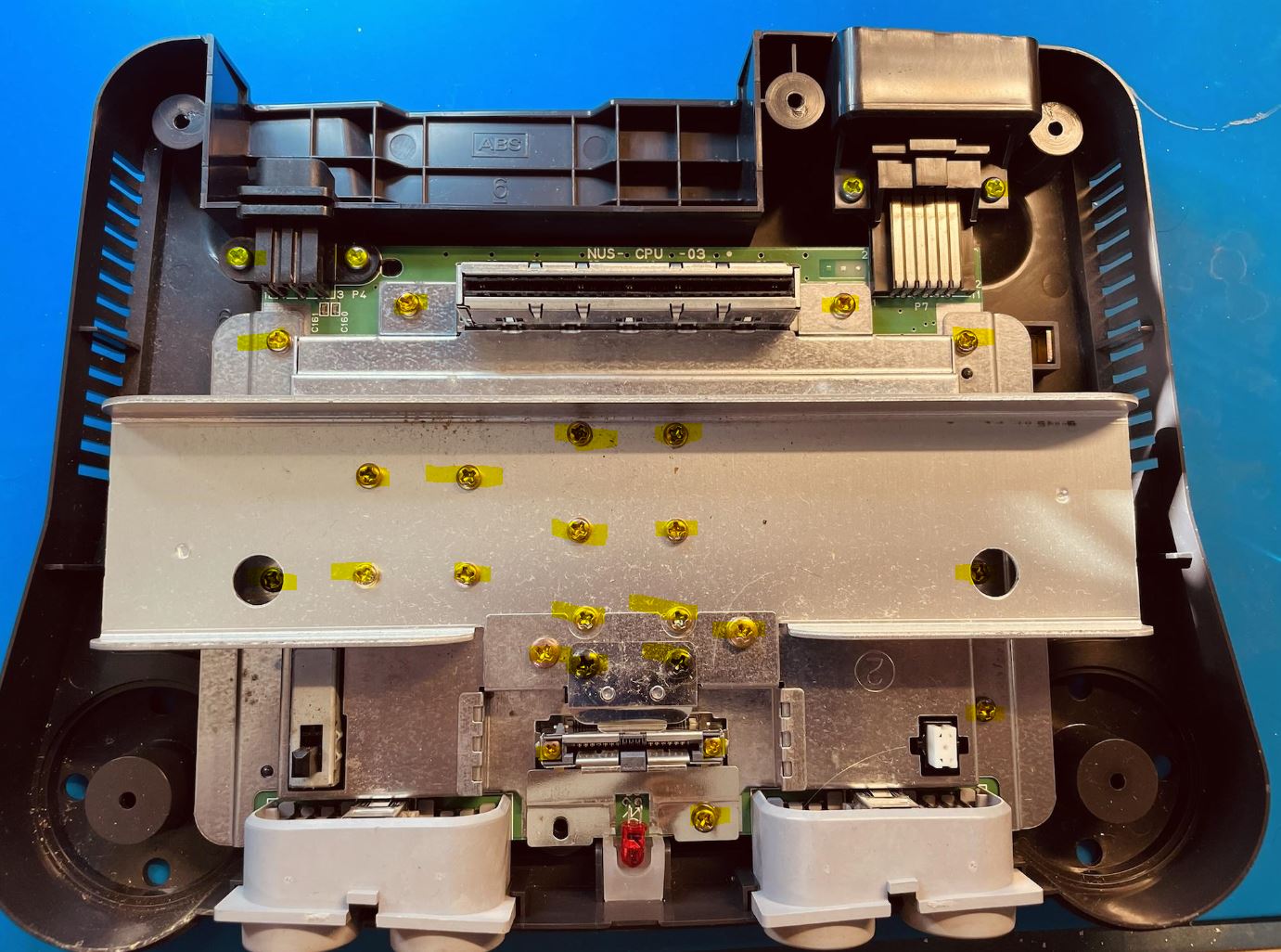
Step 1 - Console Disassembly
Click to expand/collapse
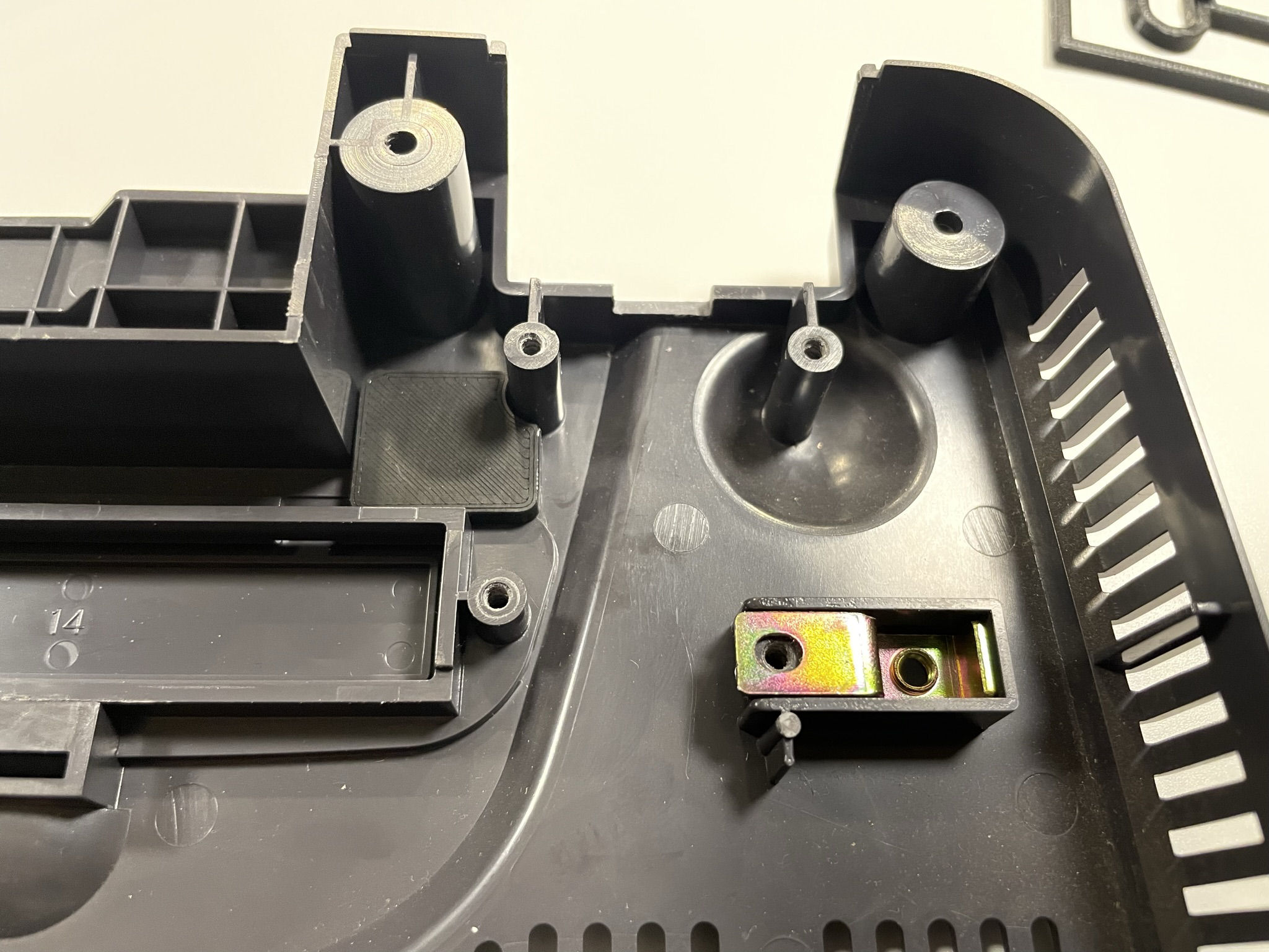
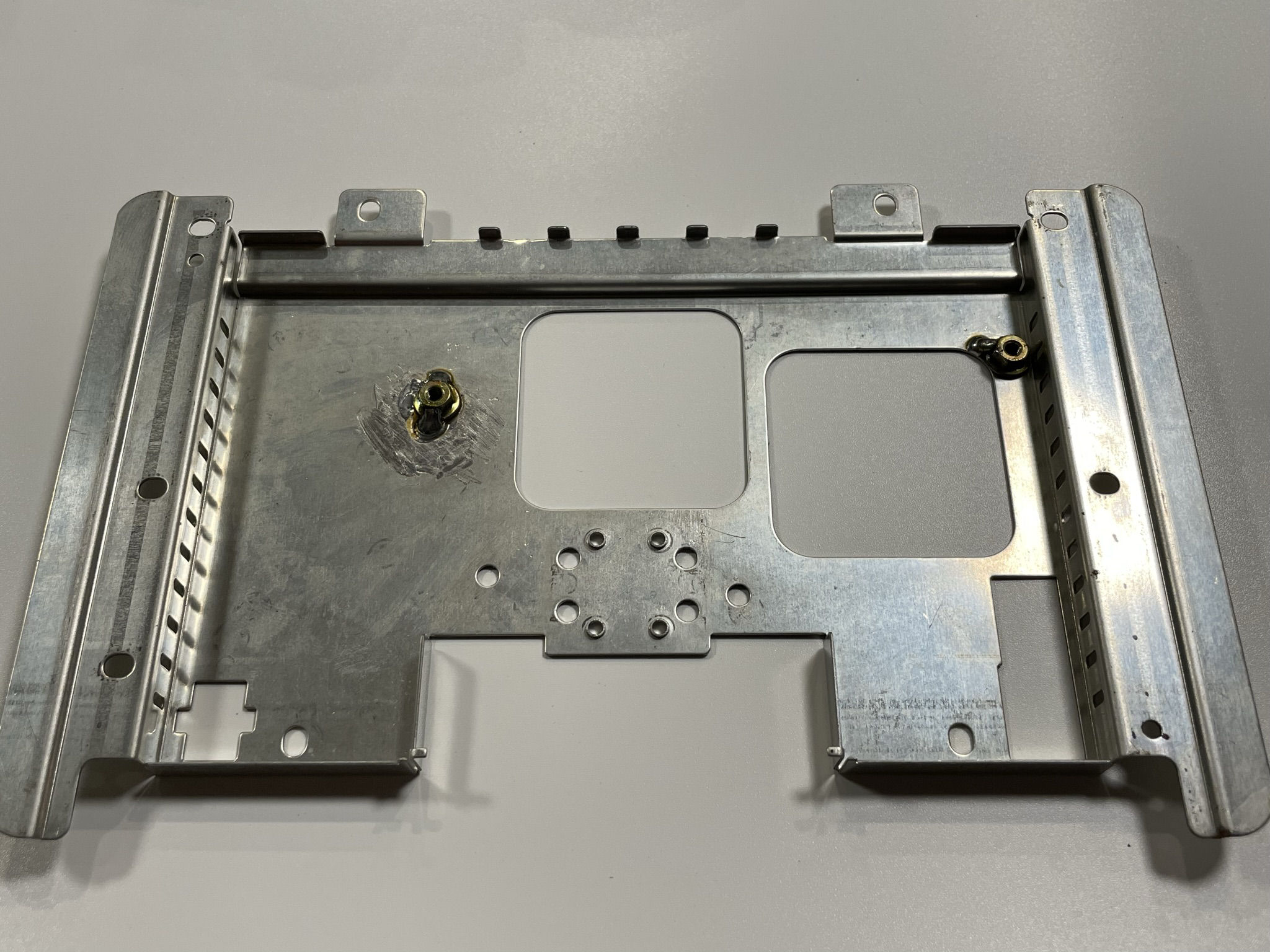
Remove all gamebit screws on the bottom of the console to remove top case.
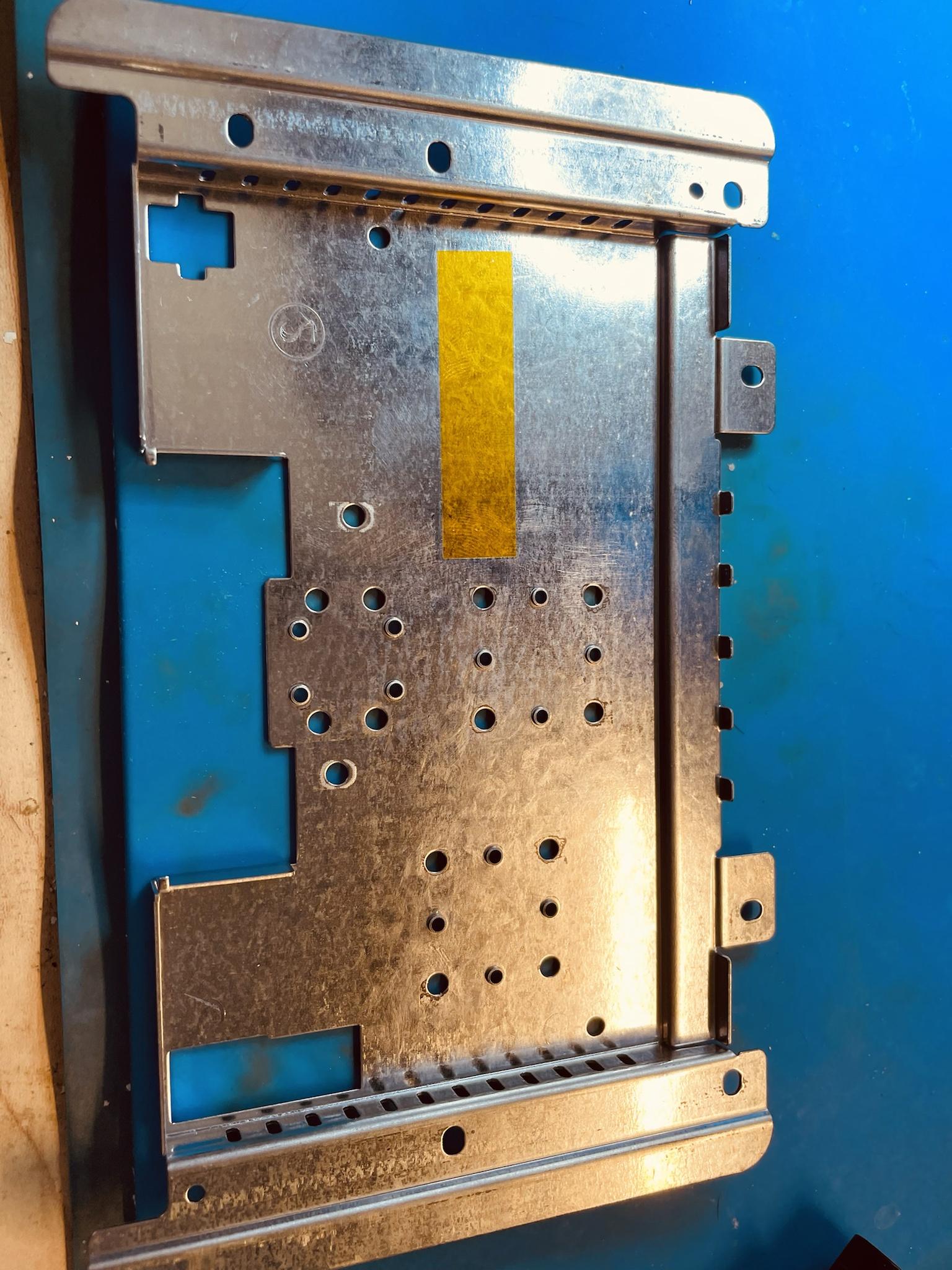
Remove all screws and remove motherboard:
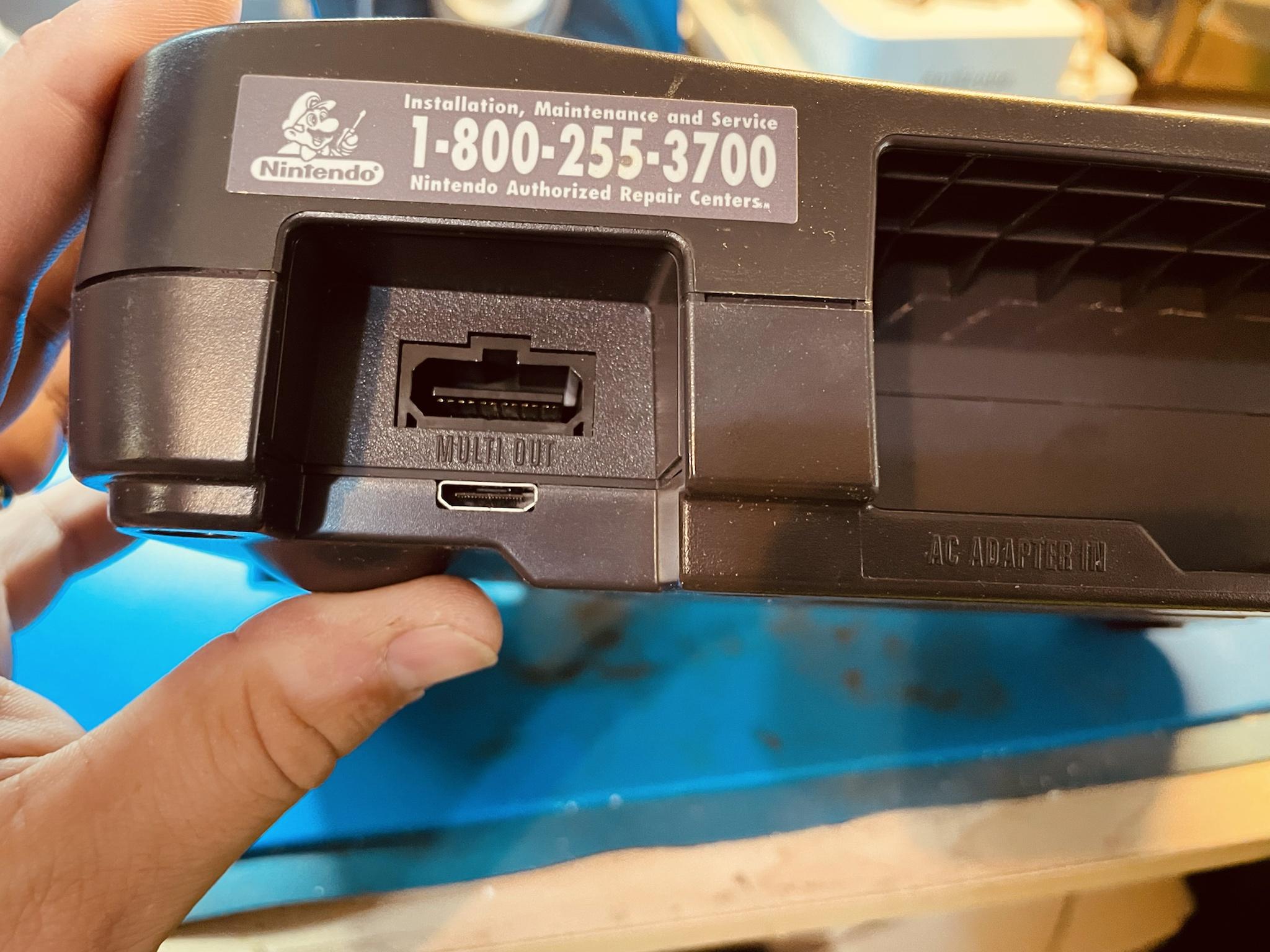
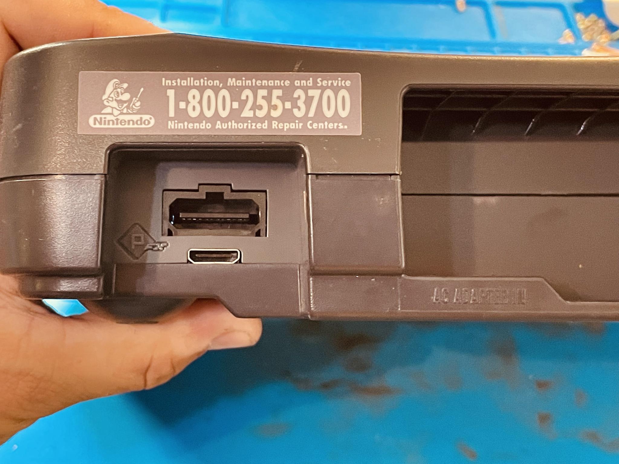
Step 2 - Creating the mini HDMI port hole
If using the no cut version, skip to Step 3
Click to expand/collapse
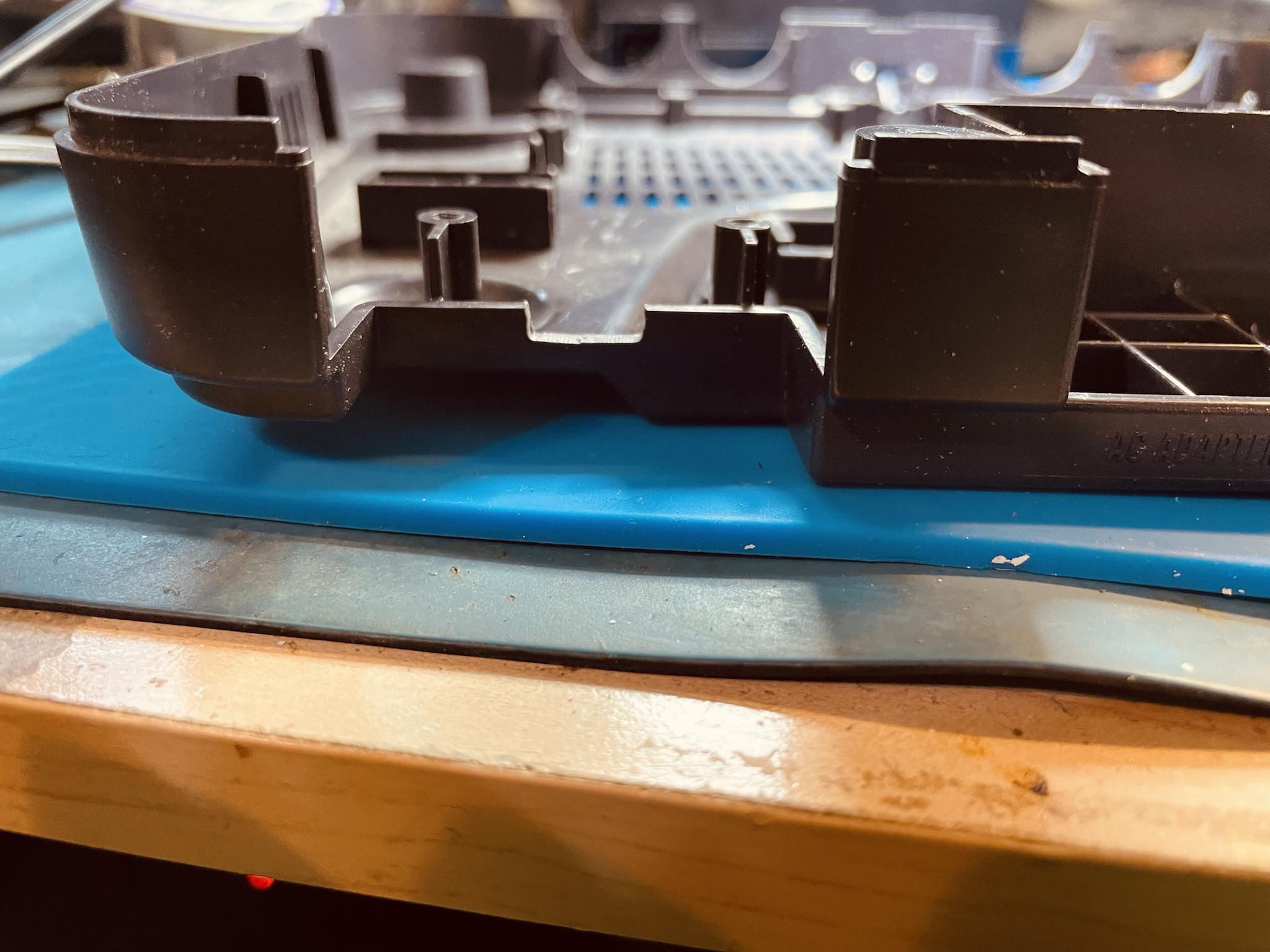
Align the N64 HDMI board in the case and lightly mark the case with an exacto knife.
Slowly carve/file out the plastic in-between the knife marks on the console
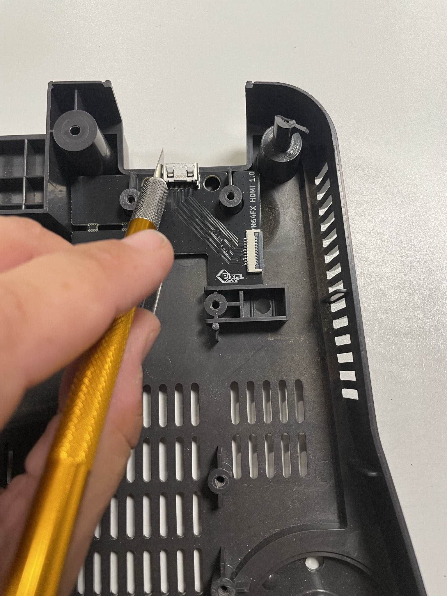
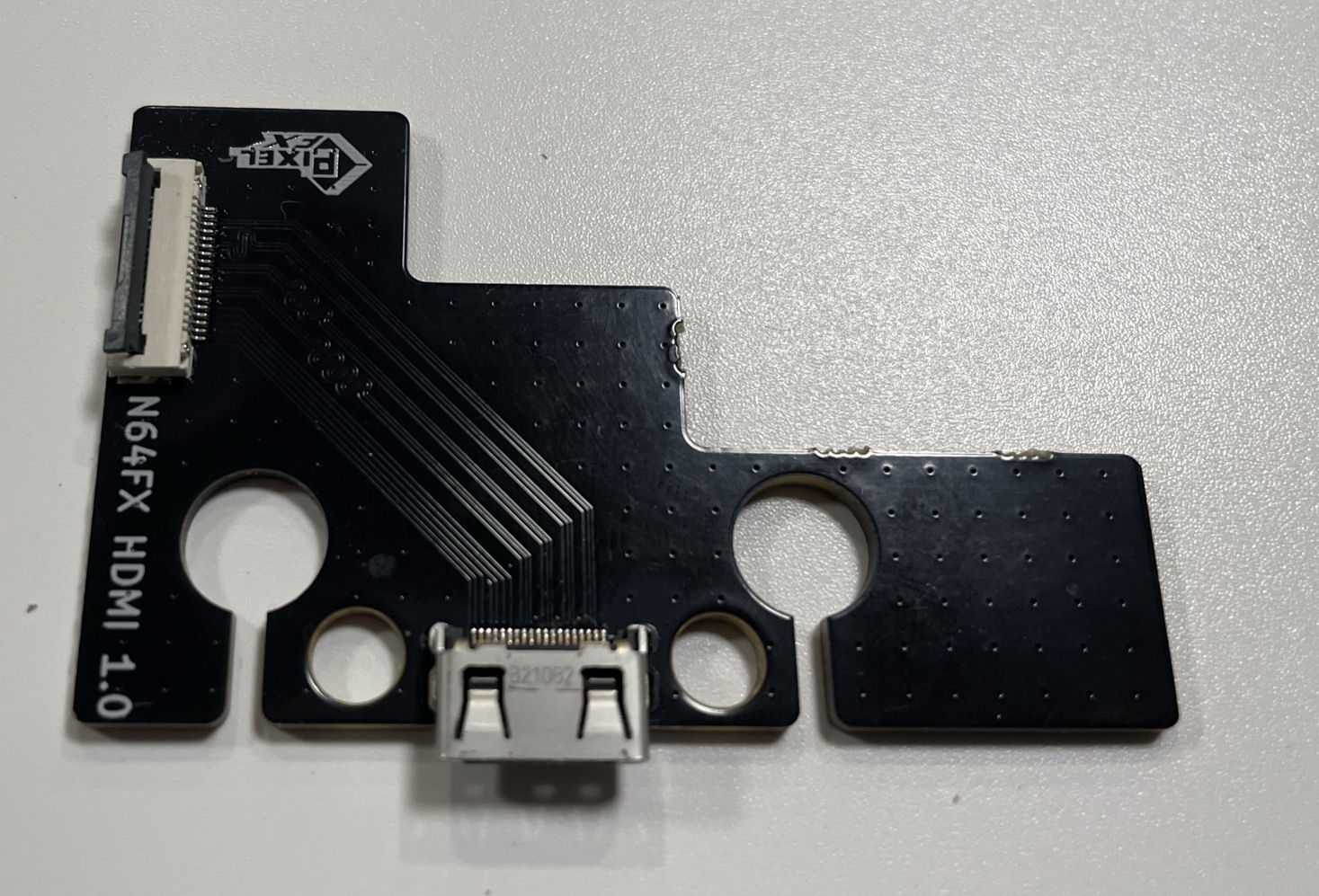
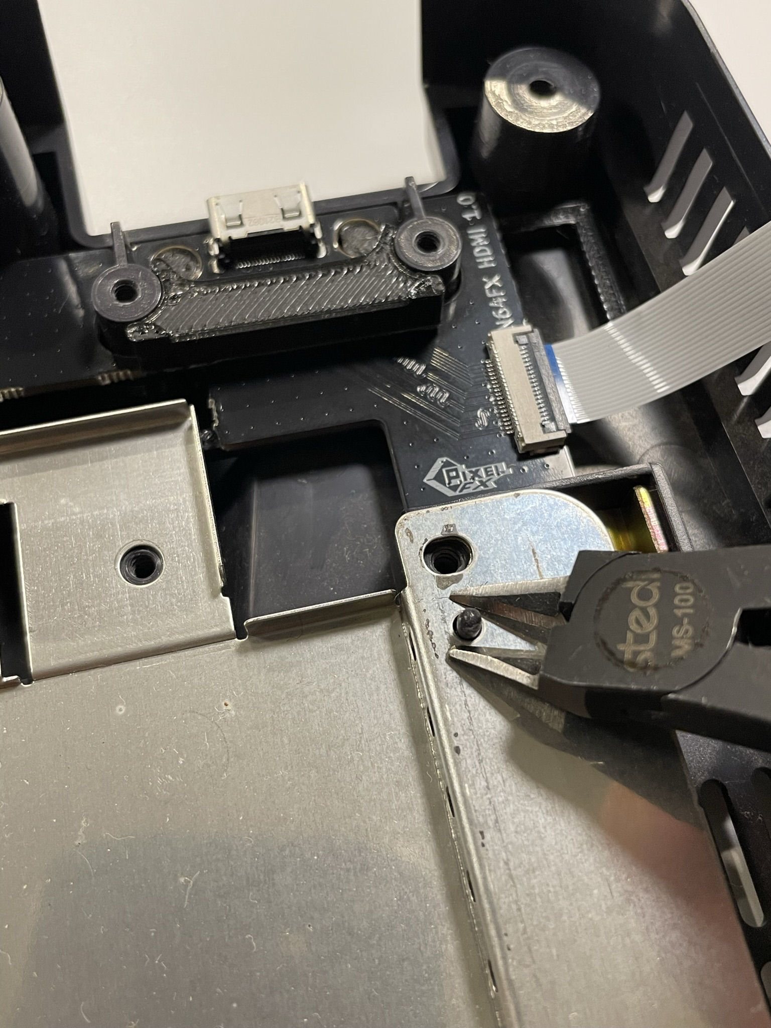
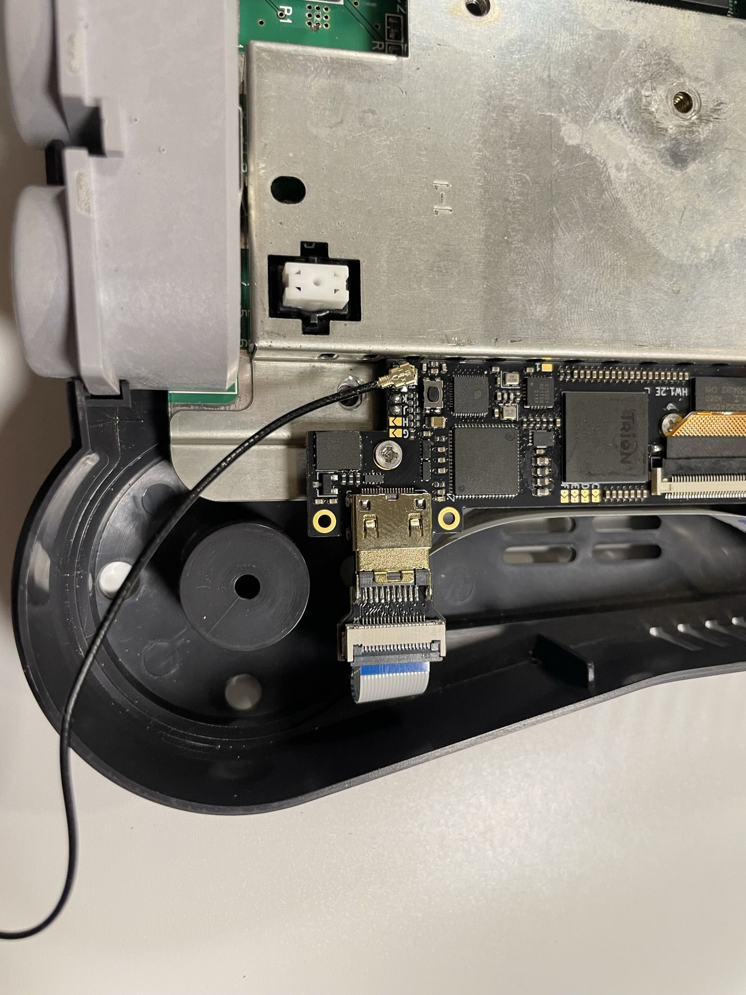
Step 3 - Installing the HDMI board
Click to expand/collapse
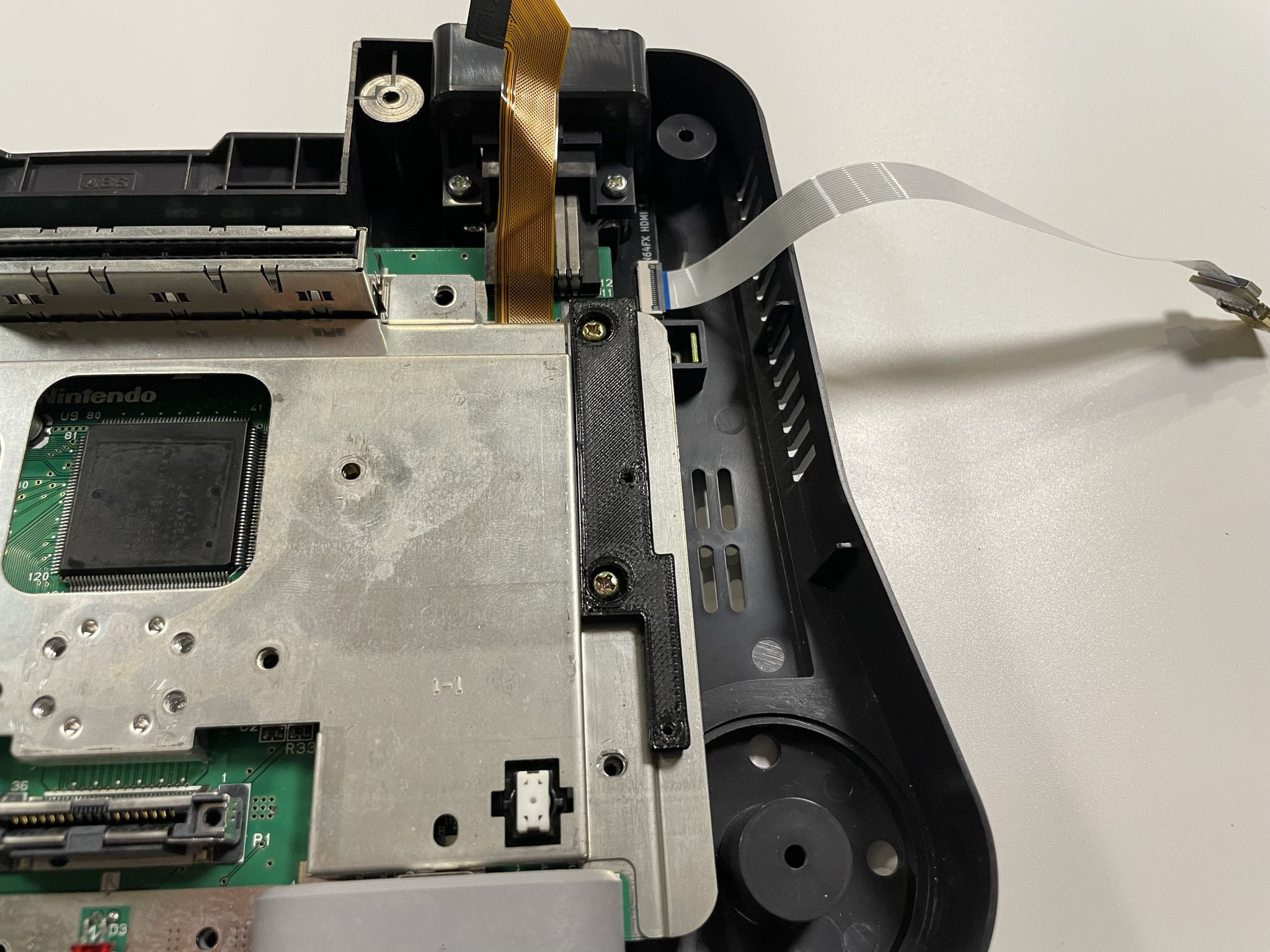
Kits sold after April 1st 2025 have new 3d plastic mount that replaces the original "N64FX HDMI"
New HDMI Mount
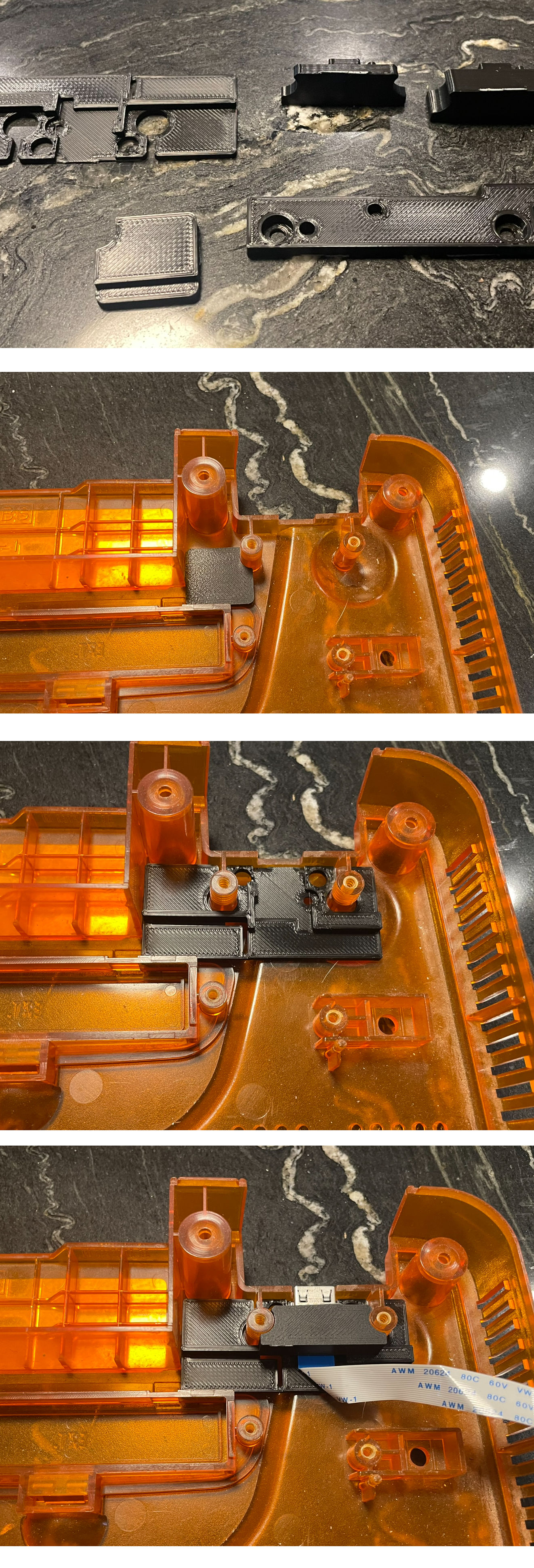
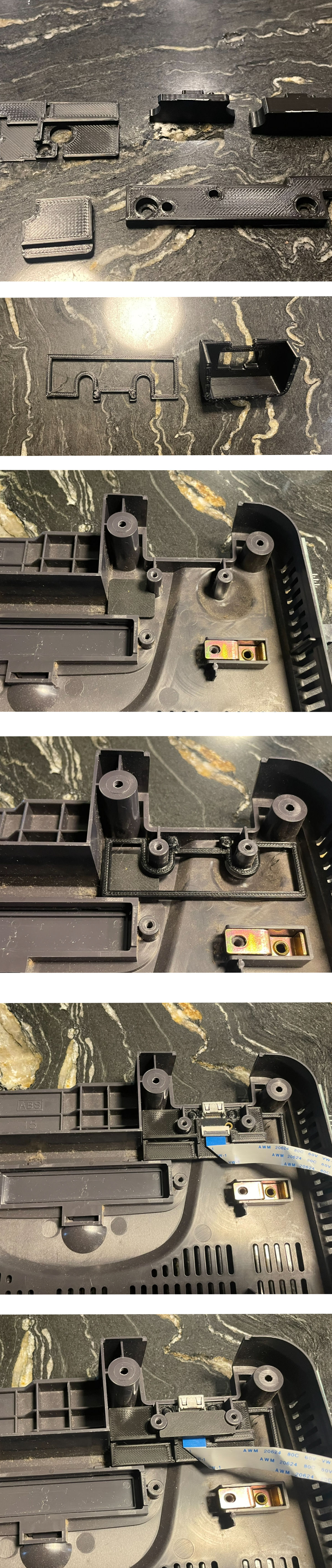
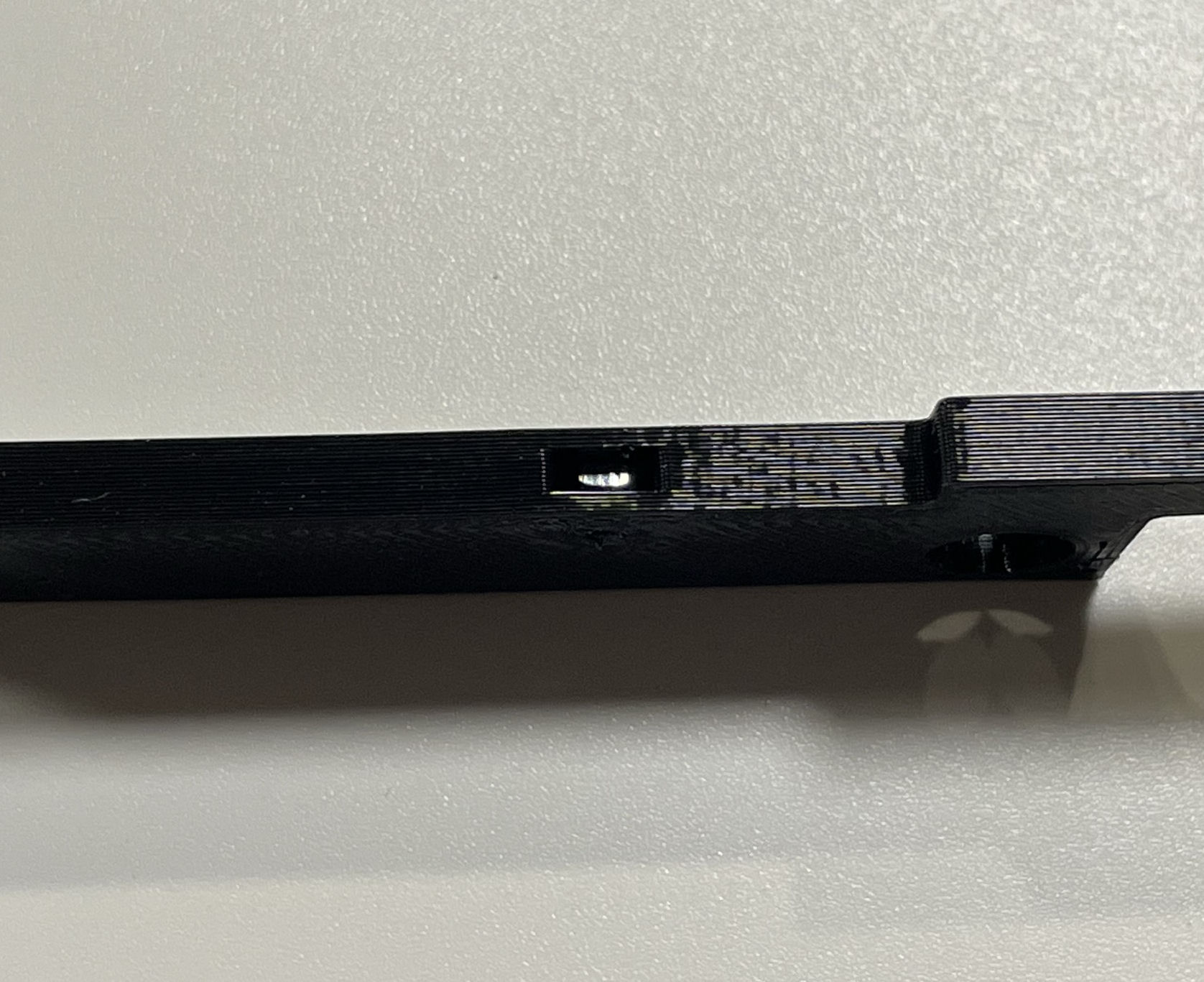
Break apart the plastic 3d part and select your version:
Cut
Follow the iamge below; once fitted with the multiout this will make the HDMI port very strong. Make sure to use the correct size spacer. The Cut uses the taller version.
No Cut
Follow the iamge below; once fitted with the multiout this will make the HDMI port very strong. The kit does not include the backplate or spacer. Links to those 3d prints is at the top of this document. Make sure to use the correct size spacer. The No Cut uses the shorter version.
Original N64DX HDMI Mount
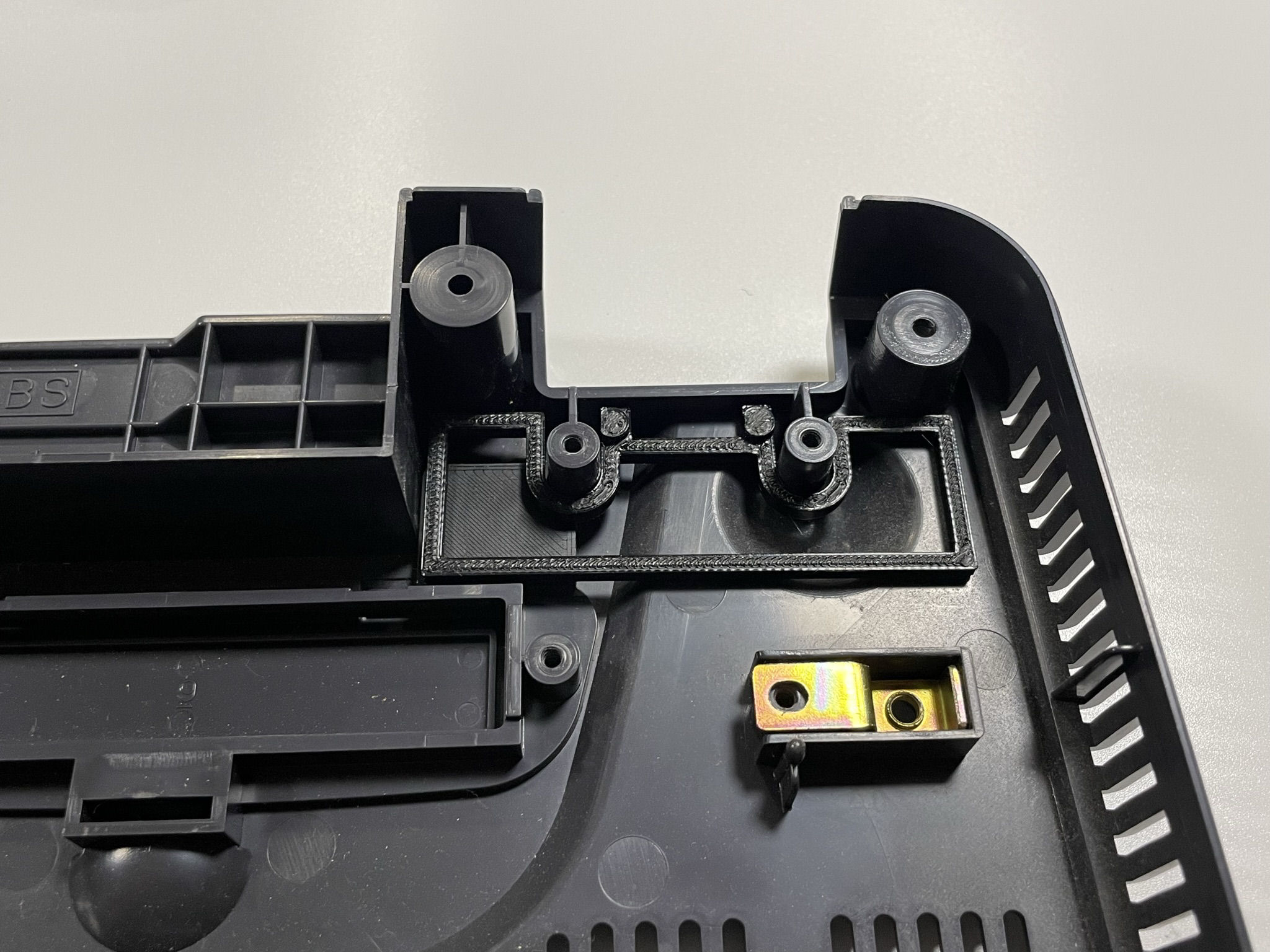
Break apart the plastic panel block:
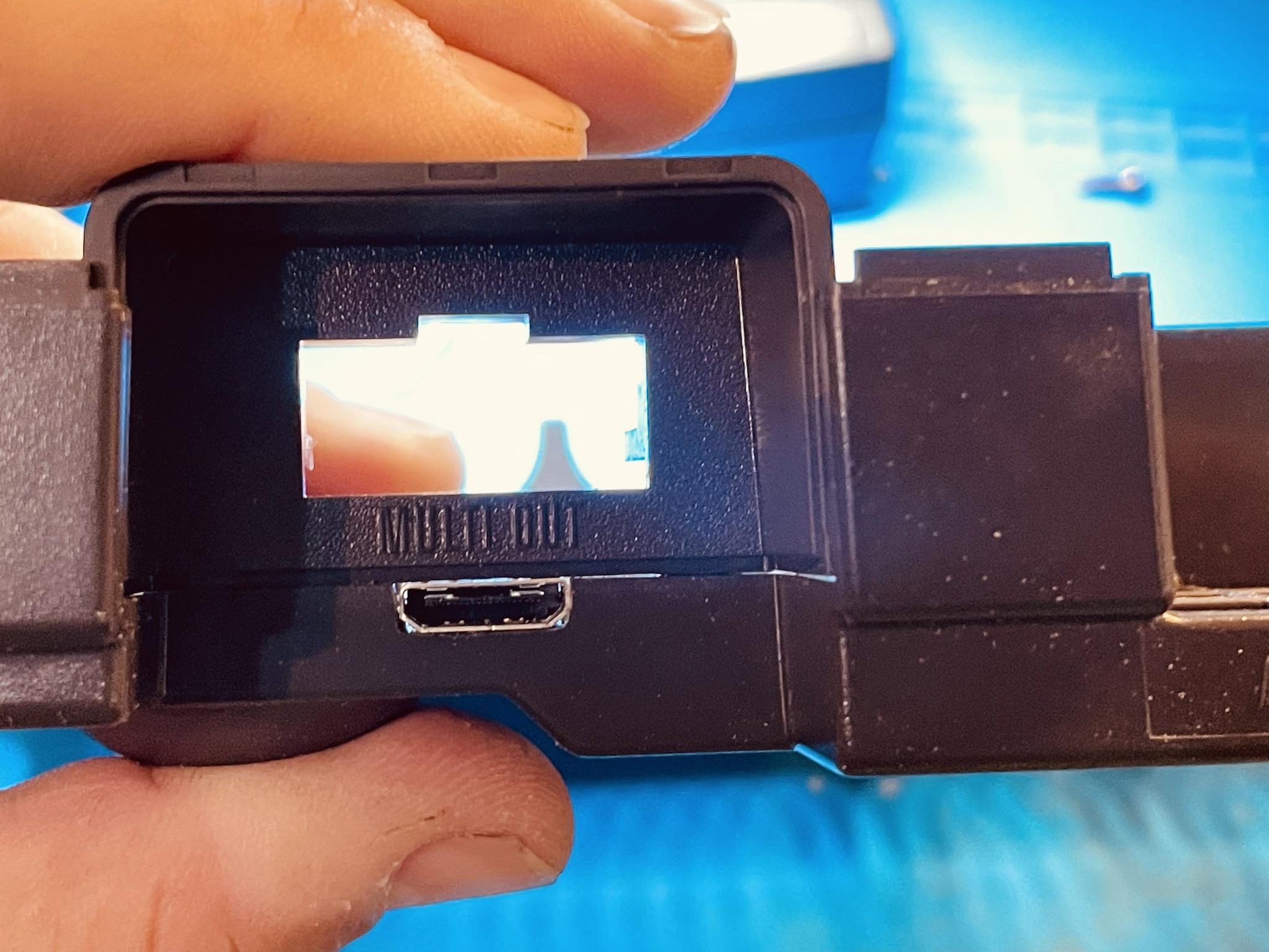
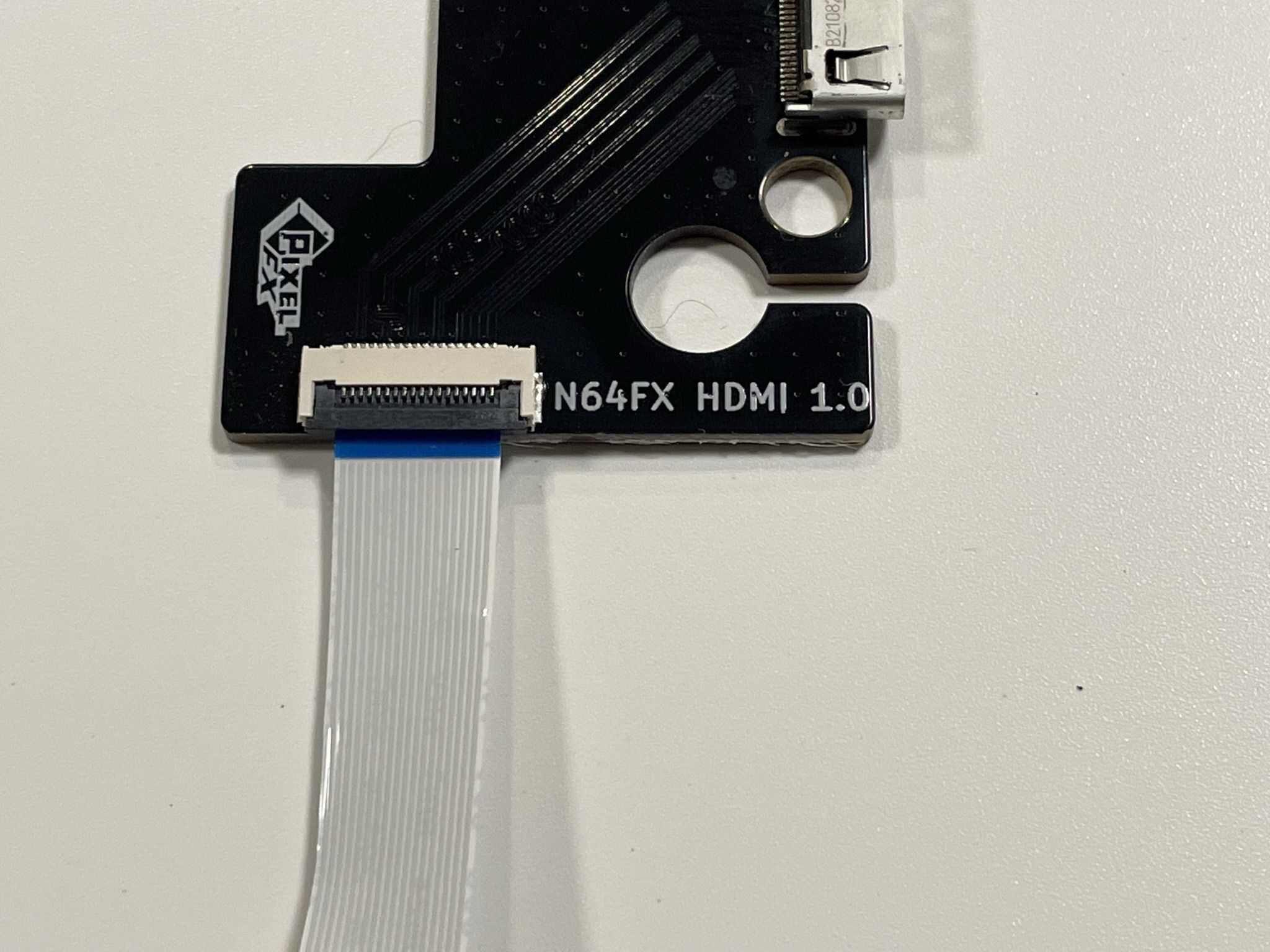
Insert the FFC cable into the N64 HDMI Board:
Be extra careful with the latching mechanism as to not break it off
Select your version
Cut
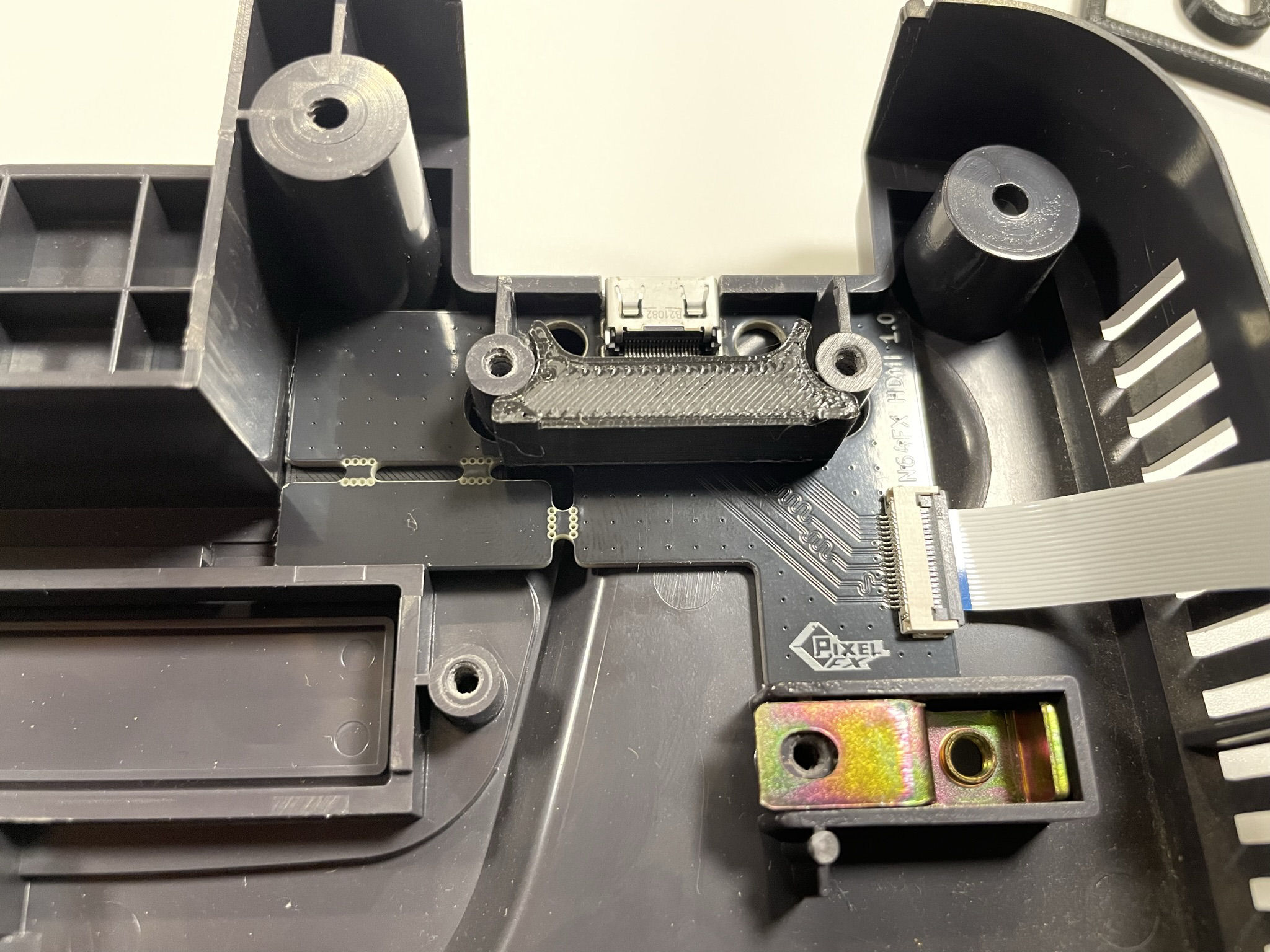
Insert the plastic block as shown:
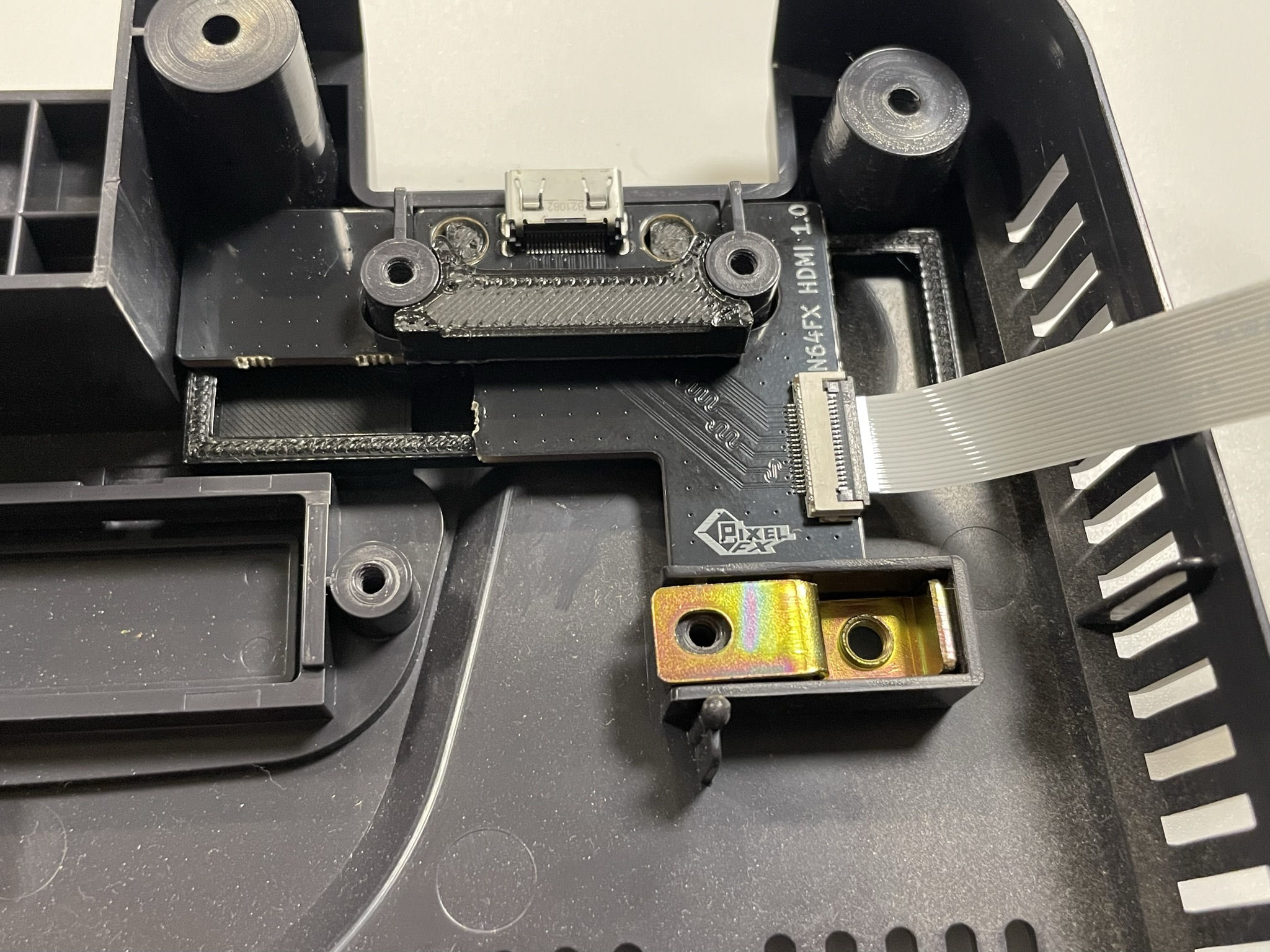
Install the HDMI board and cut spacer (Longer)
No Cut
Remove the small tab on the hdmi adapter board using side cutters.
Insert the plastic blocks as shown.
Install the HDMI board and no cut spacer (Shorter)
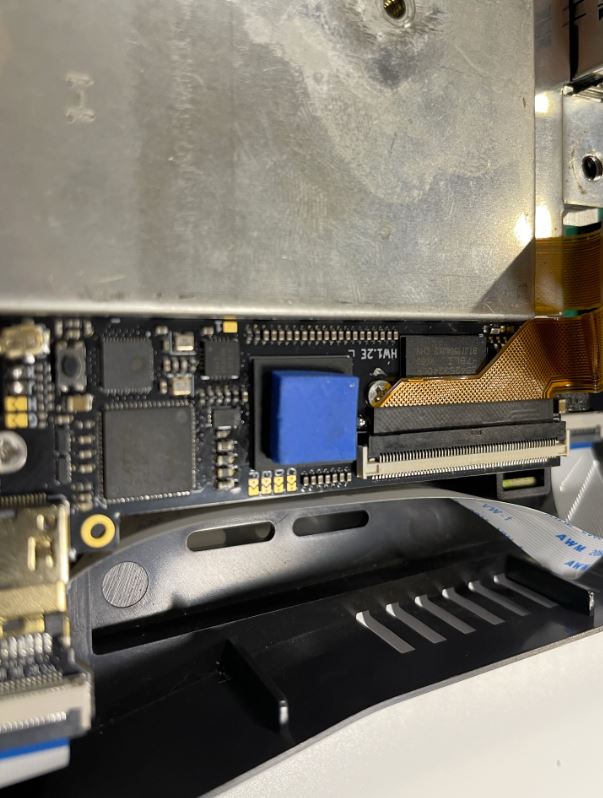
Step 4 - Soldering the RCP Flex
Click to expand/collapse
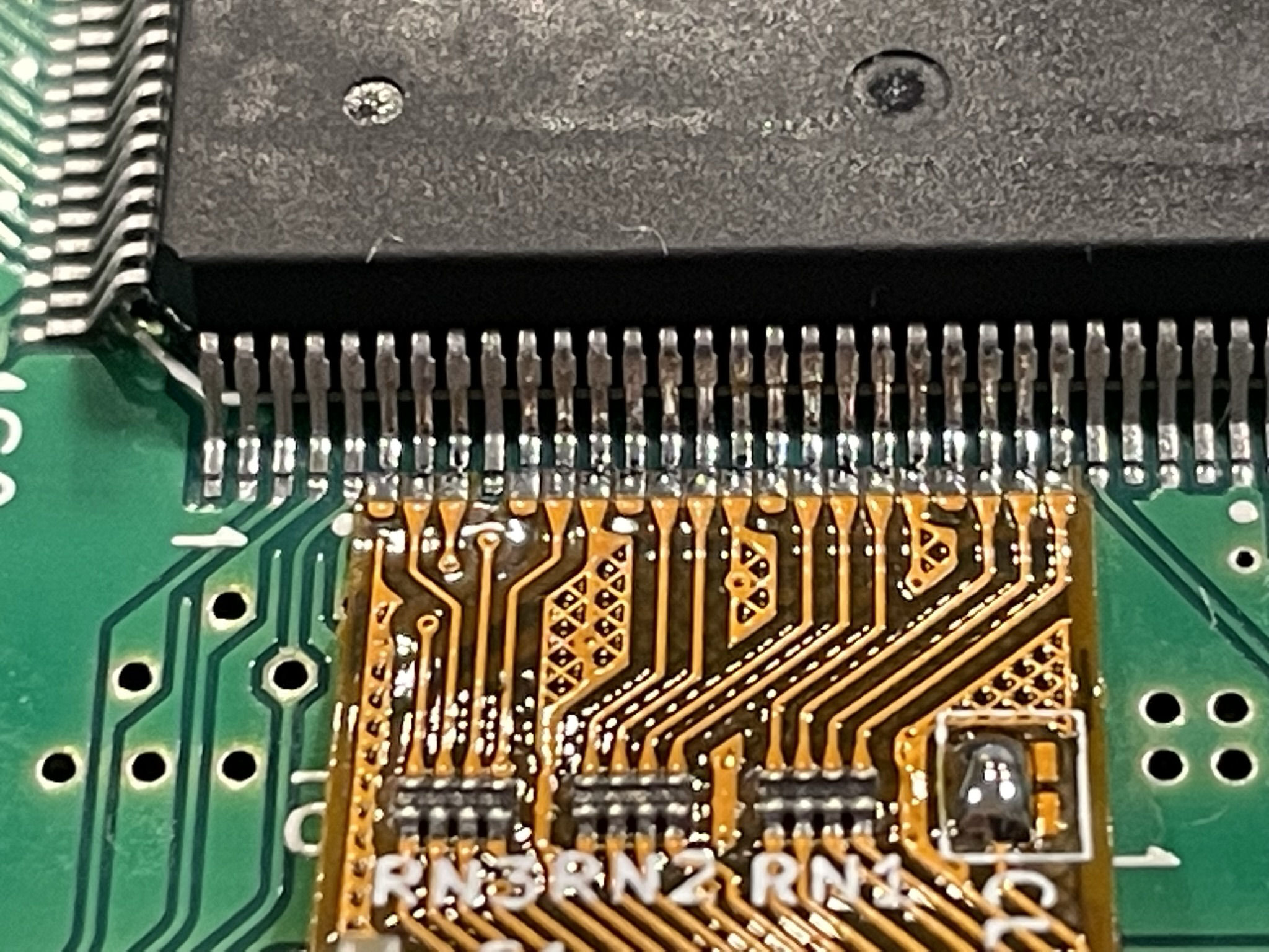
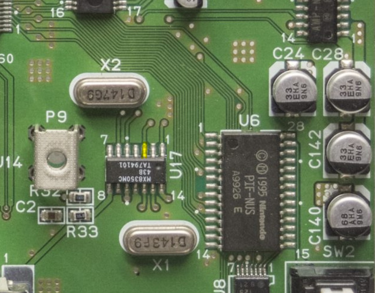
Align the flex on the RCP to pin 6.

Solder the flex cable in place keeping it flat as possible.
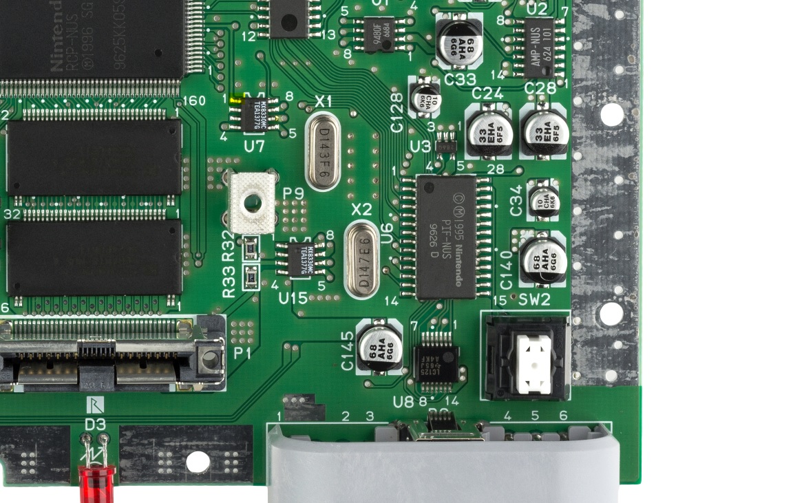
Hookup RC, RST and CON connections from the flex cable to the PIF using 30 AWG Wire. You must use wires for this, do not use the blue retro flex
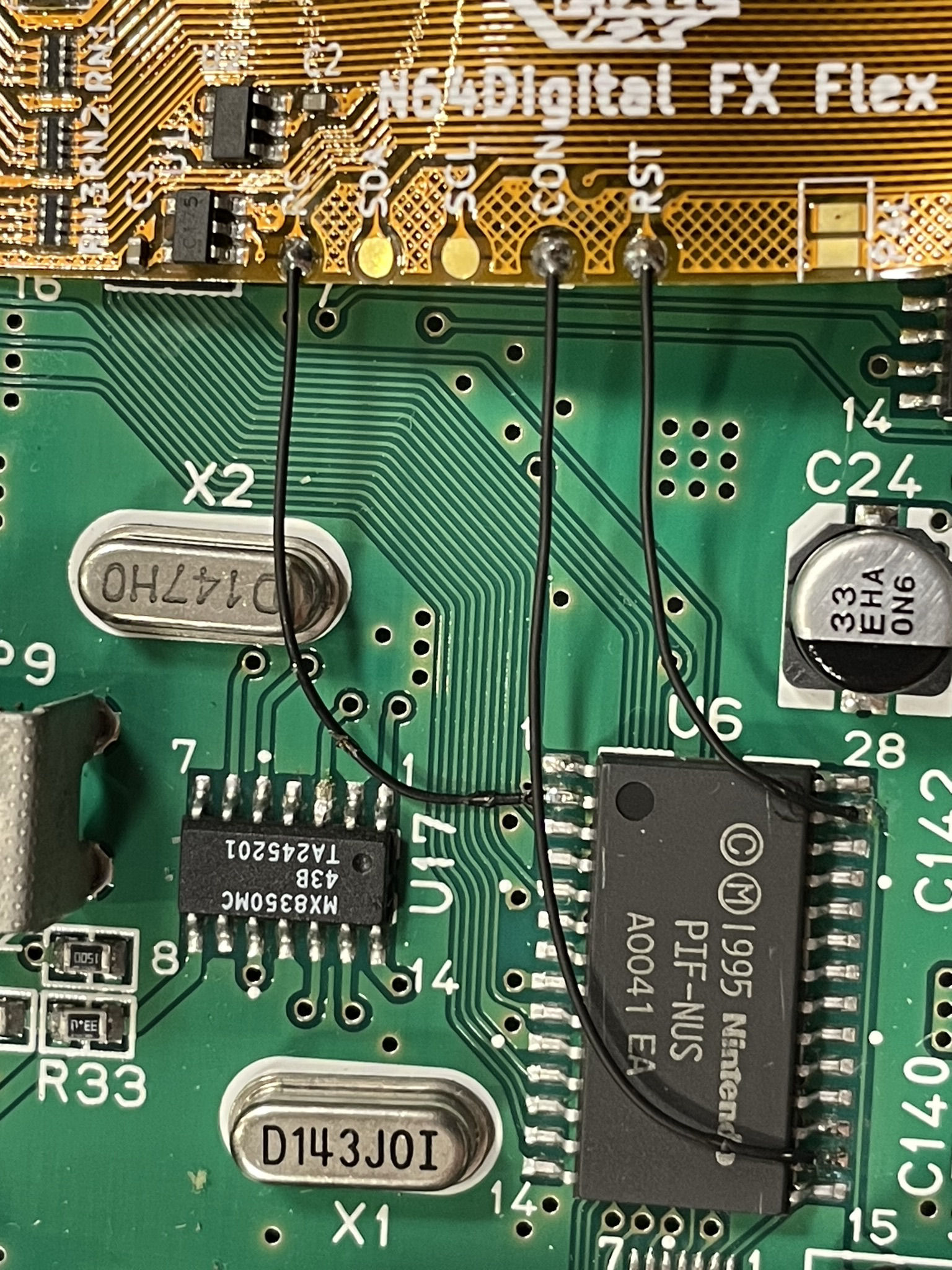
Slightly bend the RCP flex aligning it to the multiout. Refer to the image below.
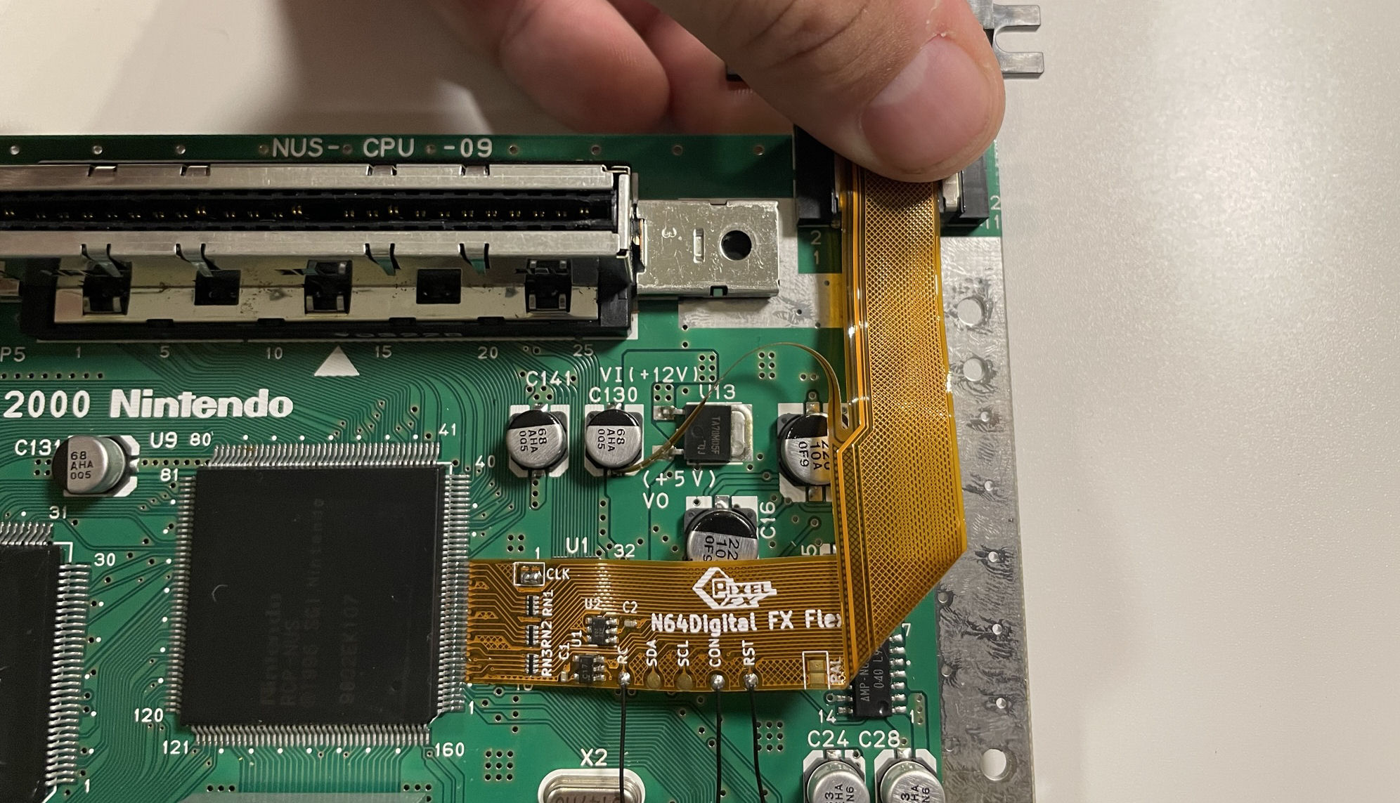
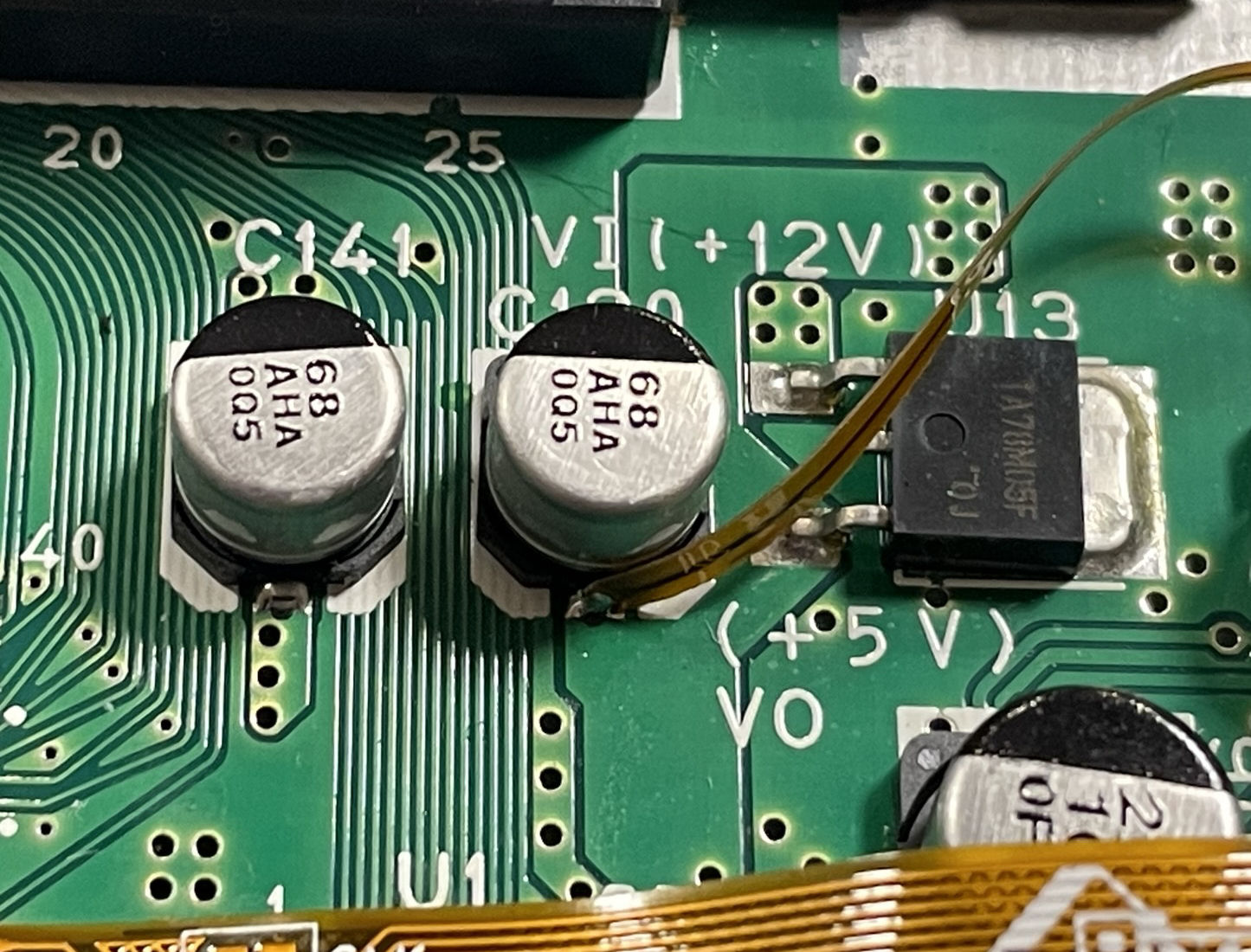
Solder the flex arm to the 5V leg. Refer to the image below.
If you have a PAL console, solder the jumper found on the Flex cable.
Step 5 - Testing the installation.
Click to expand/collapse
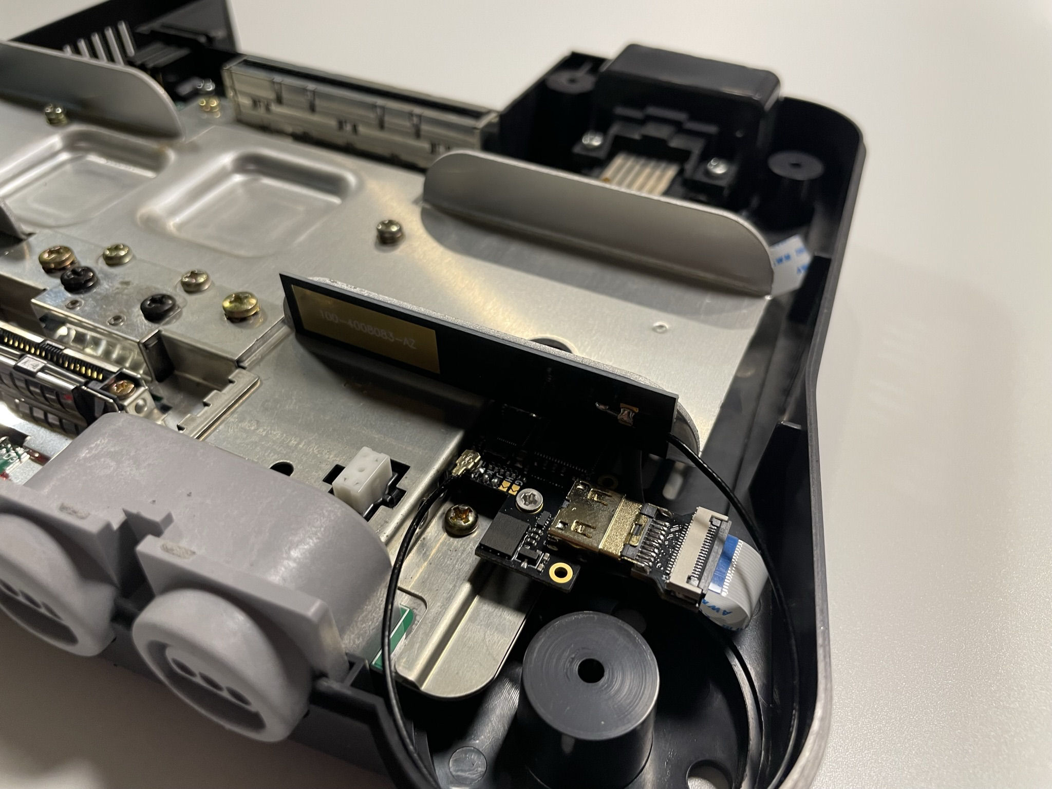
Insert the bottom shield and N64 Motherboard board back into the case.
Temporarily hookup the main flex to the retro GEM (Make sure the jumpers are set correctly)
Insert game cart, mini hdmi cable, jumper pak, and controller into port 1. Double check jumper pak is correctly oriented. Verify there is no short between 3.3V and GND before moving on.
Insert N64 power supply then power on the console. Do not leave the console powered on for more than 30 seconds since the heatsink is not installed. Verify you get an image on the screen, and open up the N64 Digital OSD using: L Trigger + R Trigger + DPad Right + C Right. Confirm everything works, including sound.
After testing, remove the game cart, power supply, controller, and jumper pak.
If you do not get video and/or audio, verify the audio/video work using a composite video cable + analog audio.
- Composite doesn't work - one of two things is wrong. Bridges on the RCP flex or a poor connection with the jumper pak / game cartridge.
- Composite does work - then the issue is related to mini hdmi to hdmi adapters. Also try another TV just to rule out any issues.
DO NOT continue on until video and audio are working properly.
Step 6 - Clock Control (Optional)
If you're not doing the clock mod, skip to Step 7
Click to expand/collapse
The N64Digital can recreate the original N64 clock that is sent to the RCP. With this control you can switch between PAL and NTSC frequencies when using an ED64 that has UltraCIC . Official games and older ED64 that use donor CIC will need a PIF replacement to boot out-of-region games.
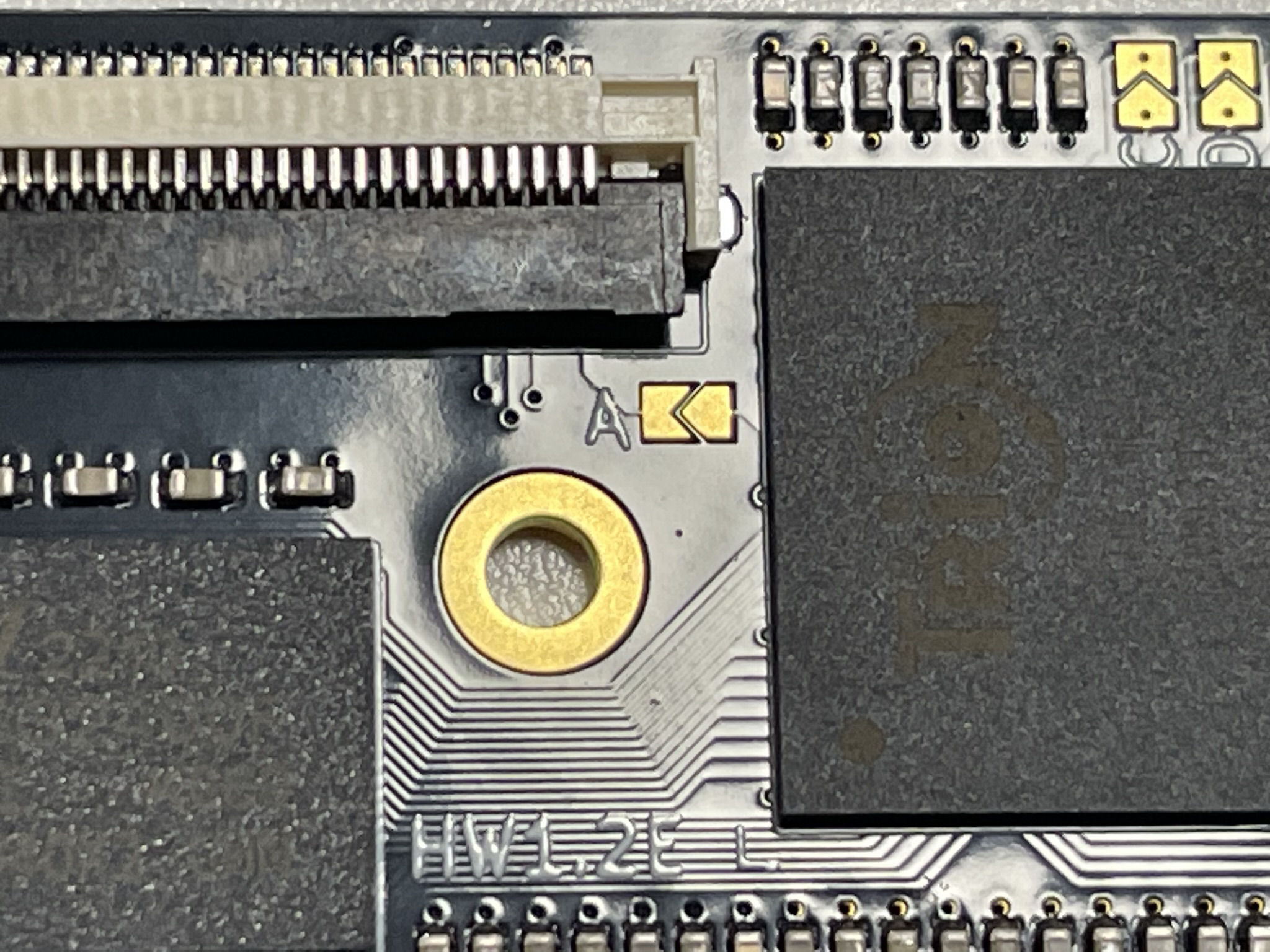
Lift the pin based on your N64 motherboard revision below.
Early NTSC and PAL consoles
Late Model NTSC & PAL consoles.
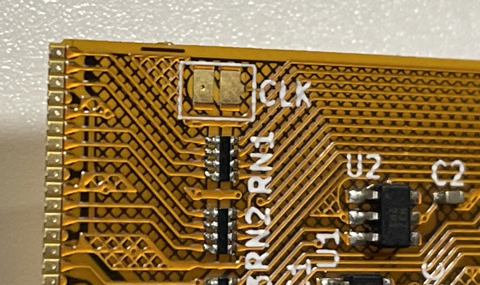
Close the CLK jumper on the Main flex cable and the "A" jumper on the GEM Board.
Step 7 - Finishing up
Click to expand/collapse
Install a small piece of kapton or electrical tape on the top shield.
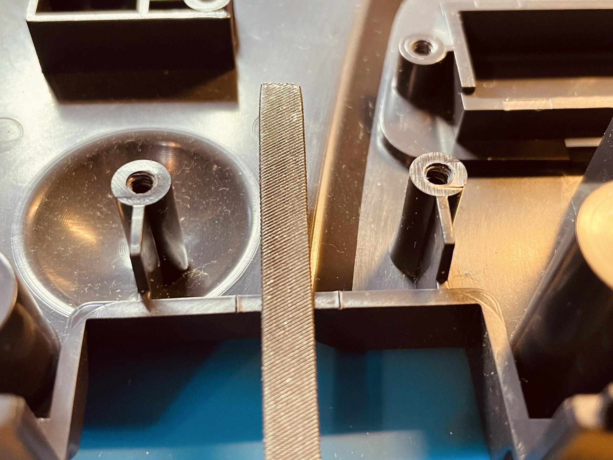
Cut the alignment pin.
Install M2 nuts into the 3D printed mount.

CPU-09 motherboards only solder the nuts to the bottom of the shield. You will need to file the zinc coating off the nuts for solder to adhear.
Install the top shield and install the 3D printed mount.
Install the IPEX antenna:
Attached the GEM board to the mount using the supplied screws *** Do not overtighten***
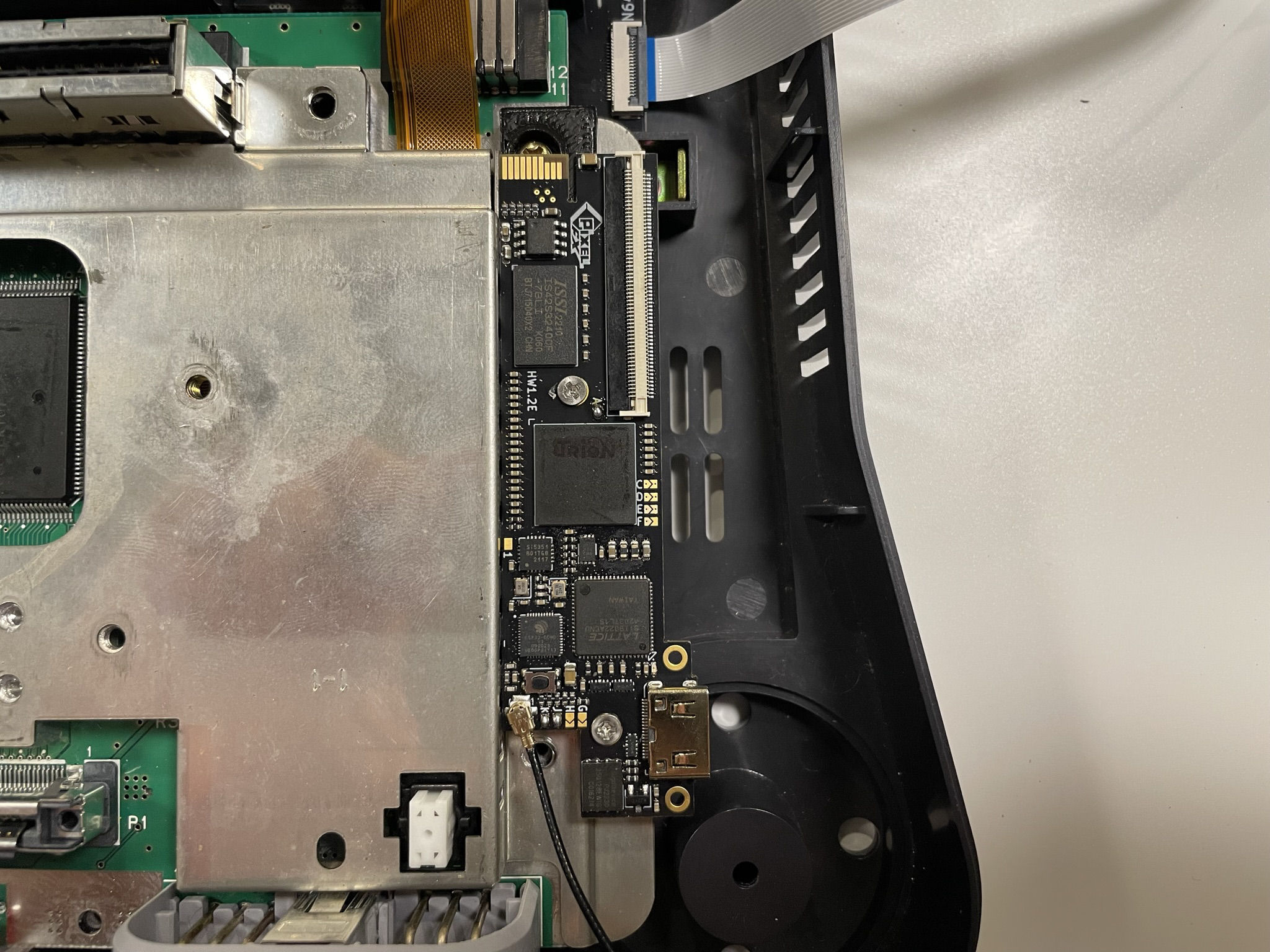
Insert the flex cable into the FFC of the male hdmi adapter.
Assemble the console in reverse order from disassembly. And install the ipex antenna and thermal pad:
Congratulations! Enjoy the Retro GEM and we appreciate your support.