Retro GEM GC Installation Instructions
Disclaimer: This kit is for advanced installers only. Install at your own risk. We cannot be held responsible for damage to your console and/or kit. Each kit is individually tested and confirmed working before being shipped.
Before you begin:
The kit is compatible with both DOL-001 and DOL-101
While the kit will work with the Pansonic Q its not outlined in the this guide. Make sure to grab Jesusburns neon Q adapter if you are doing a Q.
The doc assumes you are doing a no cut (Replace analog or digital port) installation in your gamecube.
If you are upgrading an existing GCDual or other installation and wanting to do the case cut you will need the 3D printed spacer to mount.
Blueshell3D has created a very nice 3D printed backplate that allows for fullsize HDMI in the GCDual cut location. This is a great option for people wanting to keep both ports while keeping full size HDMI at the same time.
Kit includes:
- GC Main Flex
- Full Size HDMI Adapter Board
- Male HDMI Adapter
- 150mm 18p FFC Cable
- FR4 Mount
- M1.6 Screw mount (2x)
- M1.6 Screw 3mm (2x)
- Wifi Antenna
- M2 Screw
- M2 Nut
- Plastic HDMI mount
Items required
- Temperature Controlled Soldering Iron
- Leaded Solder
- Non-Corrosive, No Clean Flux (Amtech 559 / Kester 959T)
- 99% Isopropyl Alcohol
- Multi Meter
- Exacto Knife
- Small screw phillips screw drivers
- Side cutters
Step 0 - GEM Jumpers.
Click to expand/collapse
Set the Retro GEM Jumpers and attach the wifi antenna.
Retro GEM jumper information:
Step 1 - Console Disassembly and shield modifications
Click to expand/collapse
This guide will not go over the disassembly of the GC. Guides are available online.
Once the motherboard is free (Leave the heatsink attached unless you plan to replace the thermal pads), set it to the side. We now need to decide which port you would like the HDMI to replace. This install will remove the the digital port in the DOL-001. Removing the analog port is also the same procedure.
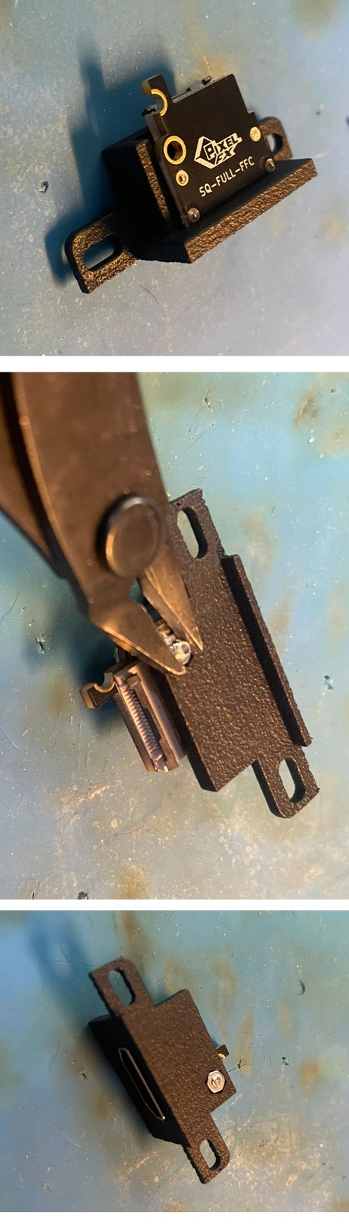
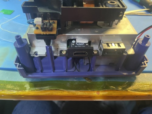
Insert the full size connector into the plastic mount. It will snap into place. Then secure the HDMI board with the M2 nut and screw. The M2 screw will need to be trimmed flush. Do not overtighten
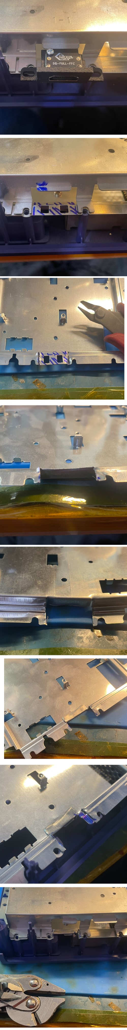
Align the top and bottom shields and check the alignment with the HDMI connector. It needs to fit in to the hole, so mark and remove any of the metal shield.
I use side cutters and pliers to cut and fatigue bend the metal off.
Step 2 - Motherboard Prep
Click to expand/collapse
No CUT port removal
Click to expand/collapse
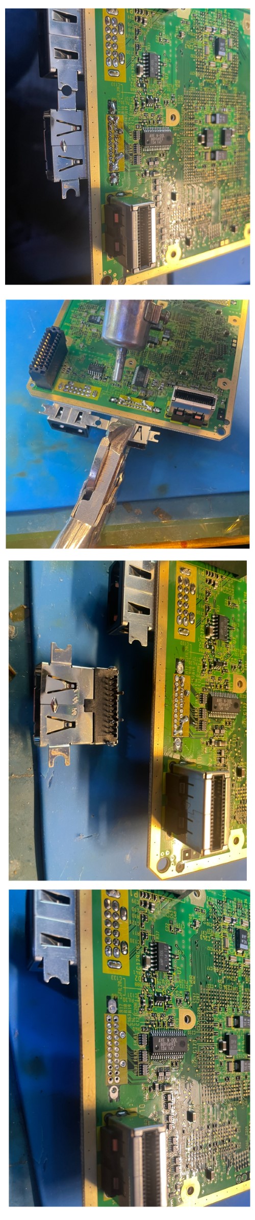
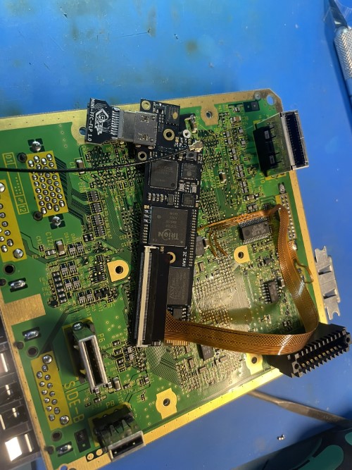
One of the video ports needs to be removed if doing the no case cut. The way I like to remove the port is to flood it with fresh lead solder and then use a hot air tool to remove the port. With the pliers I keep a steady downward force while applying hot air at an angle towards the edge. Make sure to keep moving the hot air otherwise you risk damaging the FR4. The port will come right out. There are other ways to remove the port such as desolder gun, desolder braid, quick chip etc. Do what you feel most comfortable with.
Backplate cut
Click to expand/collapse
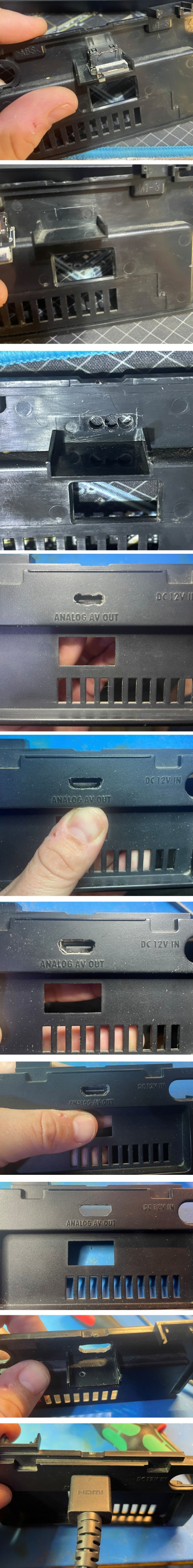
If choosing to cut the rear backplate these are the basic following steps. Use a small drill bit and small file set. Go extremely slow and always check your work.
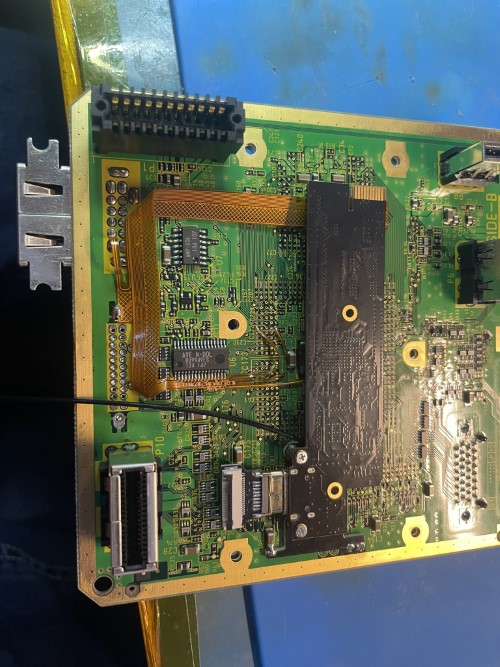
Install the mount as shown and then solder on the M1.6 screw boss. The pins are self aligning This will fit both 001 and 101 models.

Step 3 - Installing the FLEX
Click to expand/collapse
DOL-001
Click to expand/collapse
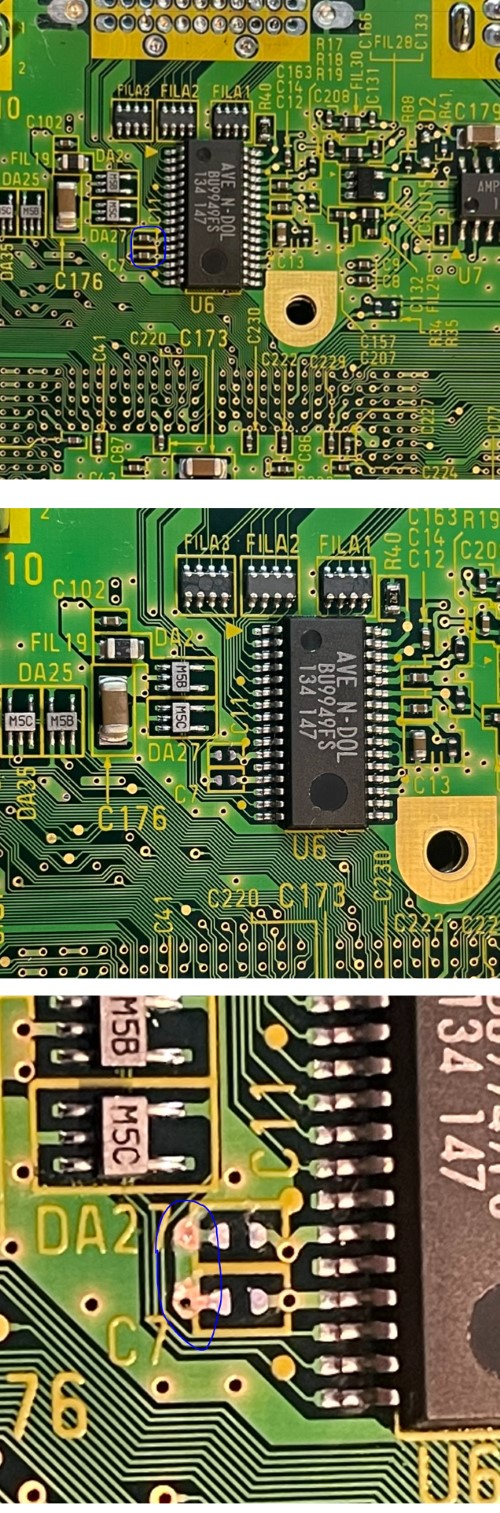
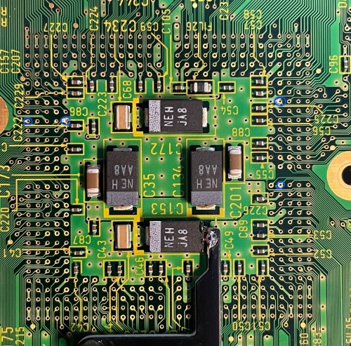
Remove the capacitors that are circled. Then use an exacto knife and remove the solder mask that is circled
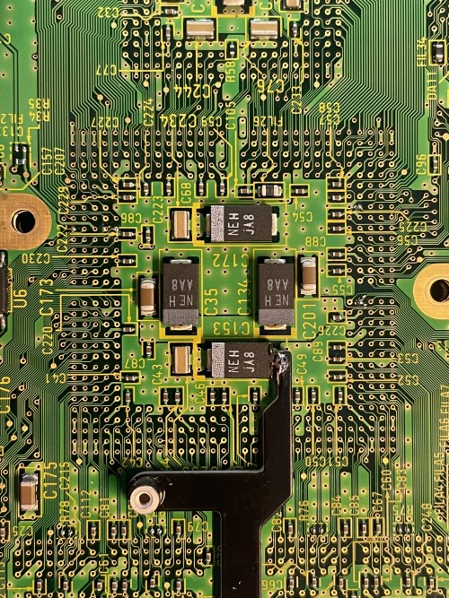
Scrape and tin the 4 vias shown below:
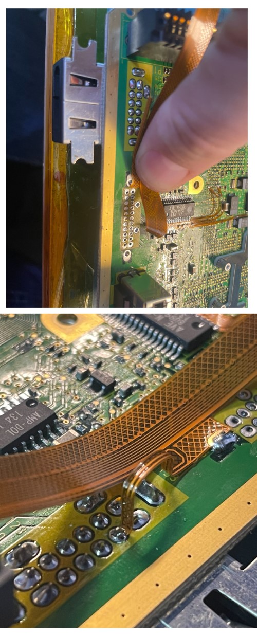
Align the main flex as shown and solder into place. Make sure to solder where you scraped by the capactiors.
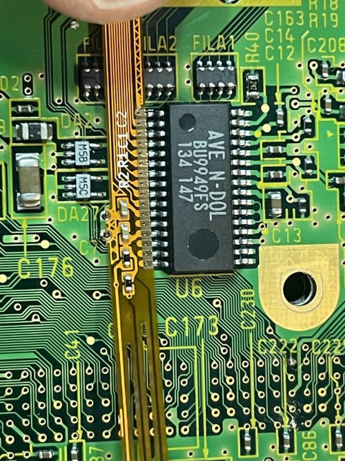

Solder the flex arms as shown. They are extremely delicate; please be careful.


Bend the flex and solder the ground support and +5v arm to the mutliout.
DOL-101
Click to expand/collapse
Scrape and tin the 6 locations shown circled. Then Install the main flex. Pay extreme attention to the vias.

Step 4 - Reassembly
Click to expand/collapse
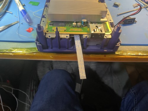
Install the FFC cable and then secure the GEM with the M1.6 screws. Make sure the male HDMI is plugged in before screwing down.
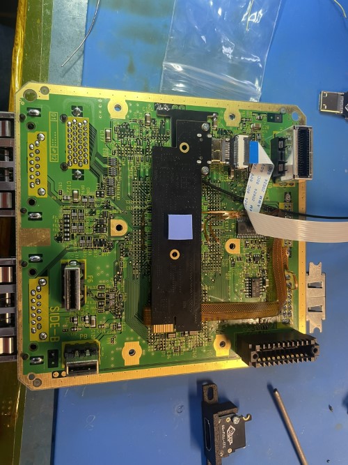
Put the thermal pad on the back of the GEM as shown. Insert the FFC connector and route to the connector you removed. If doing the GCDual mount, go out the side like existing gcdual.
Now insert the motherboard back into the GC case with the cables routed correctly.
Install the top shield and then secure the HDMI mount. It has some adjustment so you can make sure it is aligned center. Do not overtighten.

Step 5 - First Boot UP
Click to expand/collapse
Open up the OSD by using L + R + DPad R + X
Verify all your pins showing hearts in the debug menu. System -> Debug
For pinout information please visit this page: https://docs.pixelfx.co/GEM-Pinouts.html
If you made it congratulations! This is no easy feat and you should be proud.