Retro GEM DC Installation Instructions
Disclaimer: This kit is for advanced installers only. Install at your own risk. We cannot be held responsible for damage to your console and/or kit. Each kit is individually tested and confirmed working before being shipped.
Before you begin:
The kit is compatible with all VA0 and VA1. VA2 is not supported
The doc assumes you are doing a no cut (Replaces Serial or Video Port) installation in your Dreamcast. If you are upgrading an existing HW1/HW2 installation or wanting to do the case cut you will need the 3D printed HDMI holder.
Kit includes:
- DC Main Flex
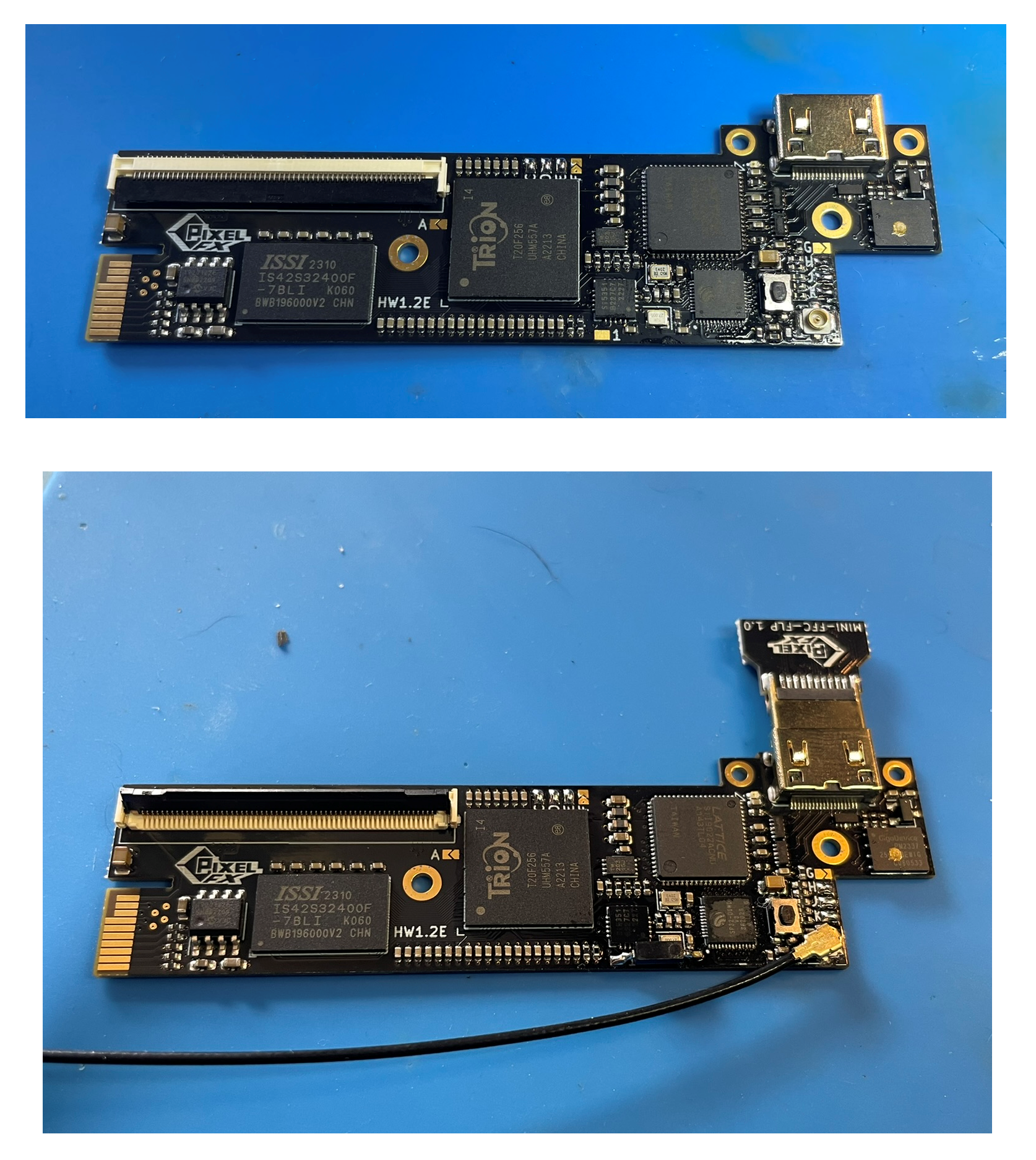
- HDMI Adapter Board
- Male HDMI Adapter
- 150mm 18p FFC Cable
- Plastic Panel block
- M2 Nuts (1x)
- M2 4mm Screw (1x)
- M1.6 3mm Screw (2x)
Items required
- Temperature Controlled Soldering Iron
- Leaded Solder
- Non-Corrosive, No Clean Flux (Amtech 559 / Kester 959T)
- 99% Isopropyl Alcohol
- Multi Meter
- Miniature File Set & Exacto Knife (Cut Version)
- Kapton Tape
- 30 AWG wire
- Small screw phillips screw drivers
Step 0 - GEM Jumpers.
Click to expand/collapse
Set the Retro GEM Jumpers and attach the wifi antenna as shown.
Retro GEM jumper information:
Step 1 - Console Disassembly and shield modifications
Click to expand/collapse
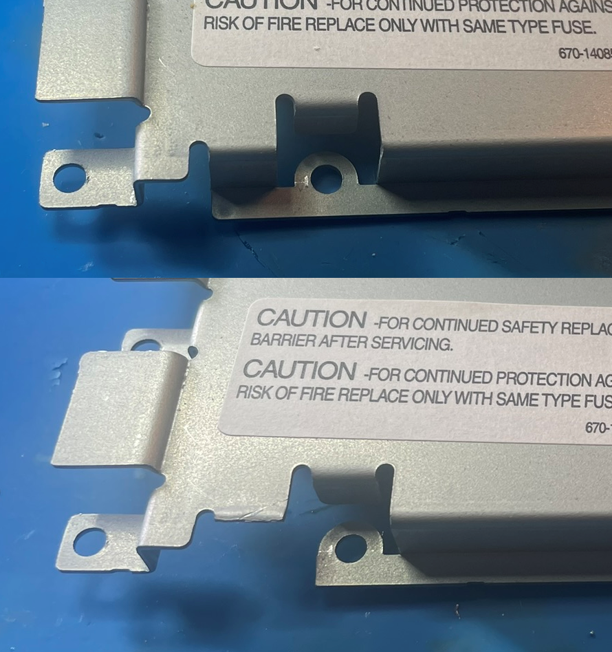
This guide will not go over the disassembly of the DC. Main guides are available online. Once the unit is torn down the following shield modifications need to be done:

Step 2 - Installing the GEM
Click to expand/collapse
The default option for the mini HDMI can either be installed into the serial or video port for a no cut option.
Cut
Click to expand/collapse
The mini HDMI can also be installed in the default DCDigital location (Cut Case). For cutting help please refer to the original DCDigital Installation
No Cut
Click to expand/collapse
The no cut option requires the video port to removed. This can be accomplished with solder wick. **Hint** Since there are no through hole joints the port can be rocked back and forth.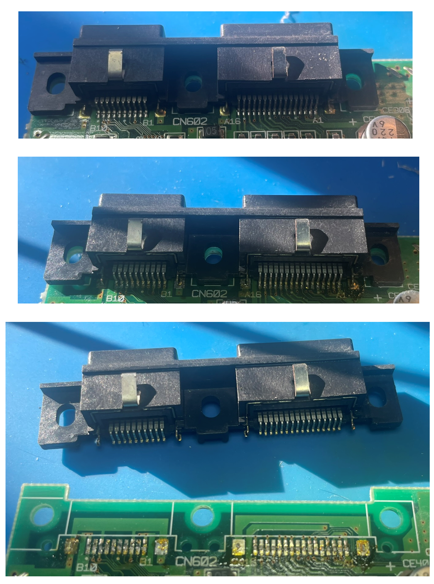
Remove the plastic material as shown. This plastic is brittle so be extremely careful. Hint Use a very sharp cutting cool. Solder the port you want to keep back onto the motherboard. Make sure it is aligned. (I am replacing the serial port in these pictures)
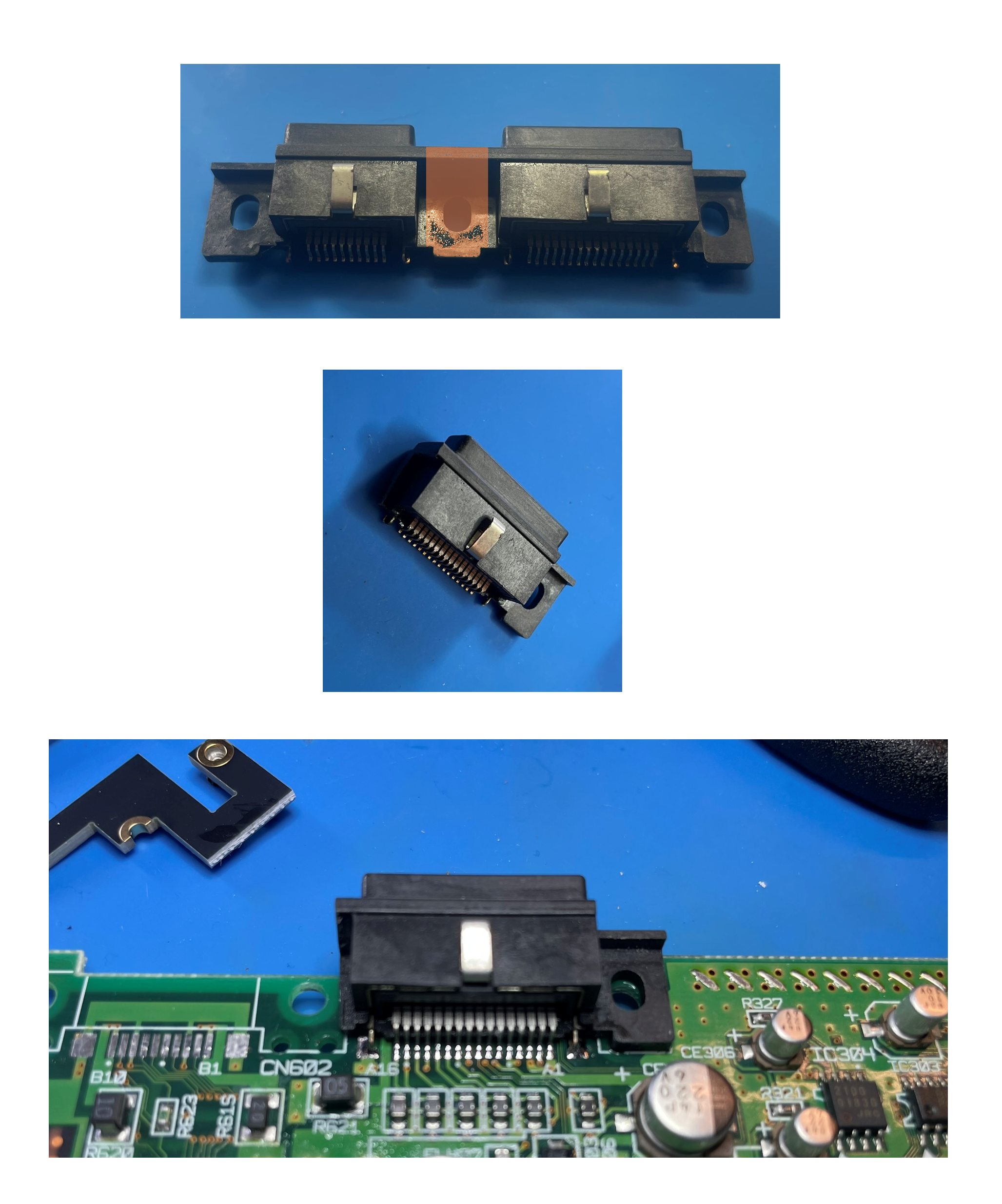
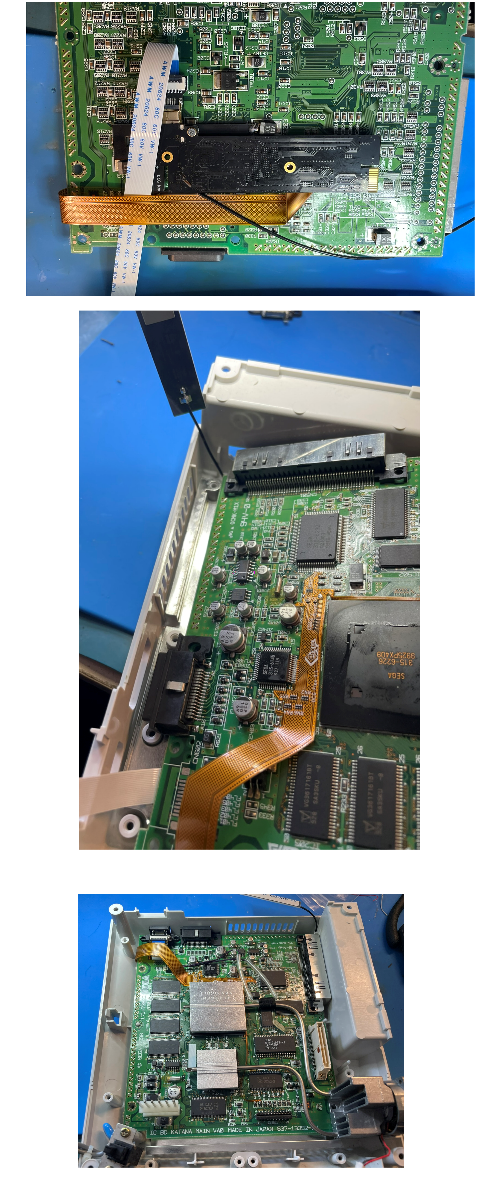
Next the GEM mount needs to be installed on the bottom of the motherboard. (VA0 motherboards: the mount won’t perfectly sit flat due to some components. This is OK. VA0 shown below.) Remove any kapton tape that is on the mount screw posts.
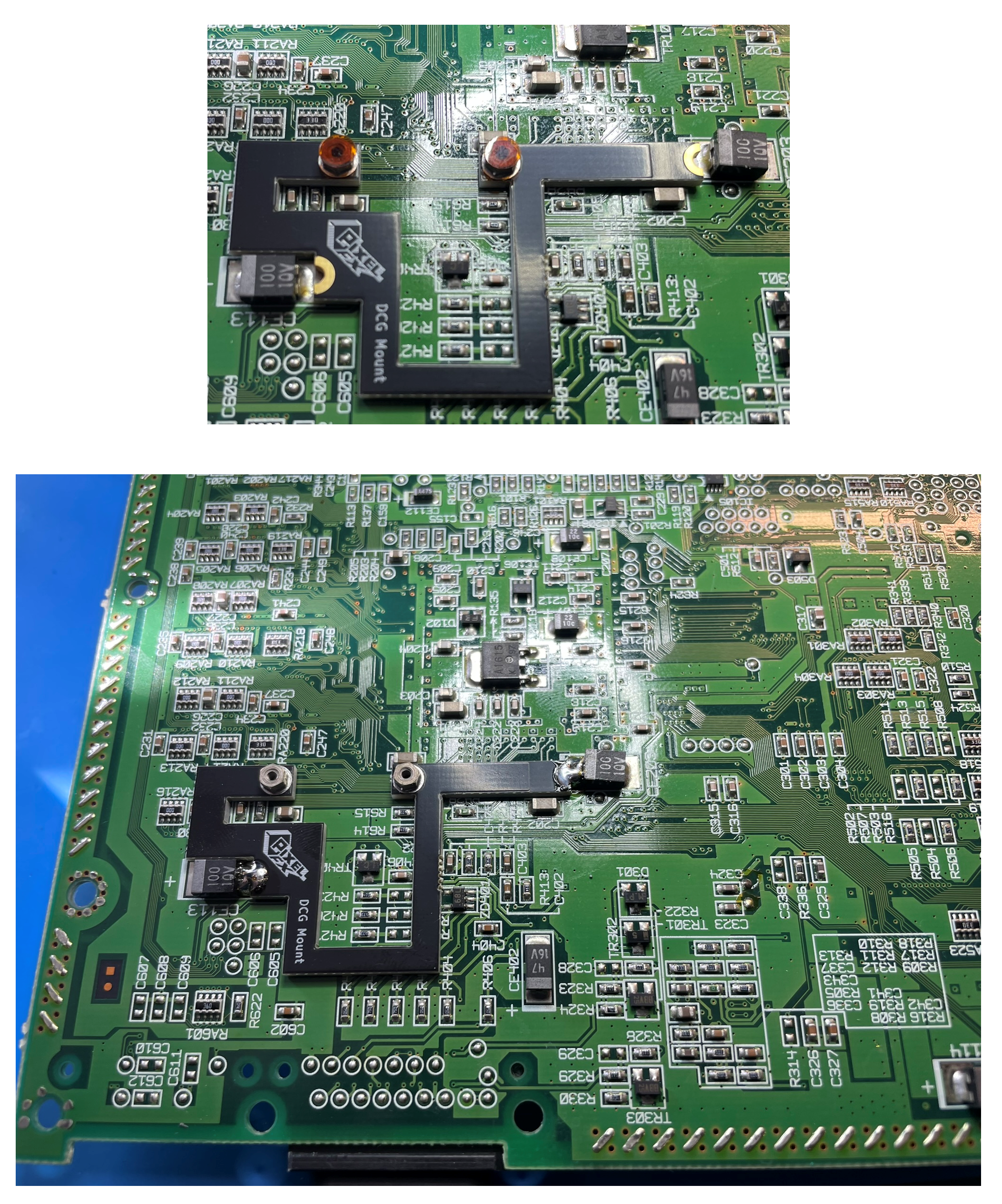
Some areas on the top side of the motherboard need to be prepped for the main flex.
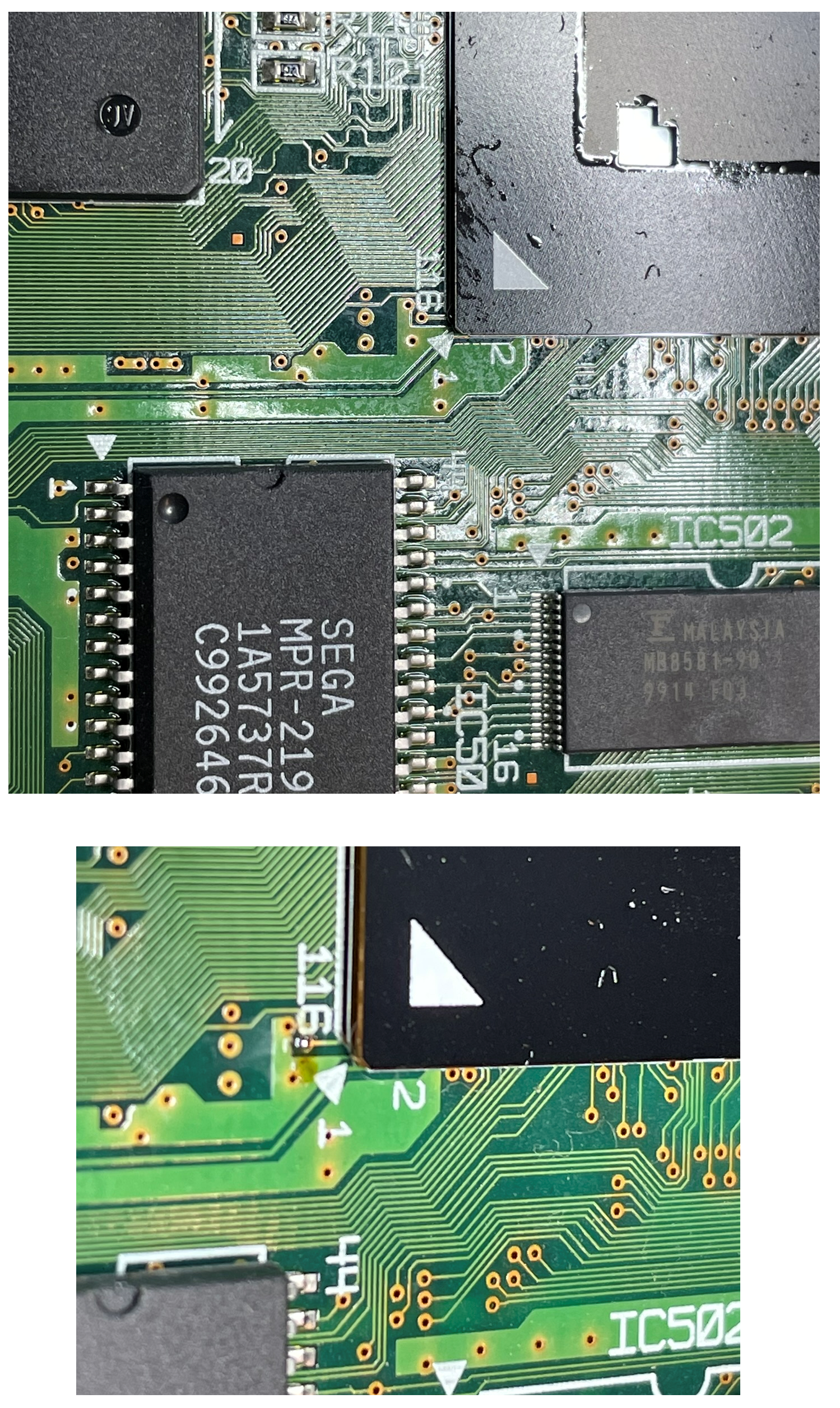
Remove the solder mask off the via by the GPU 116 text. Apply solder to the via after removing the mask. (This is the reset connection point)
Apply a little bit of solder to the controller connection points.
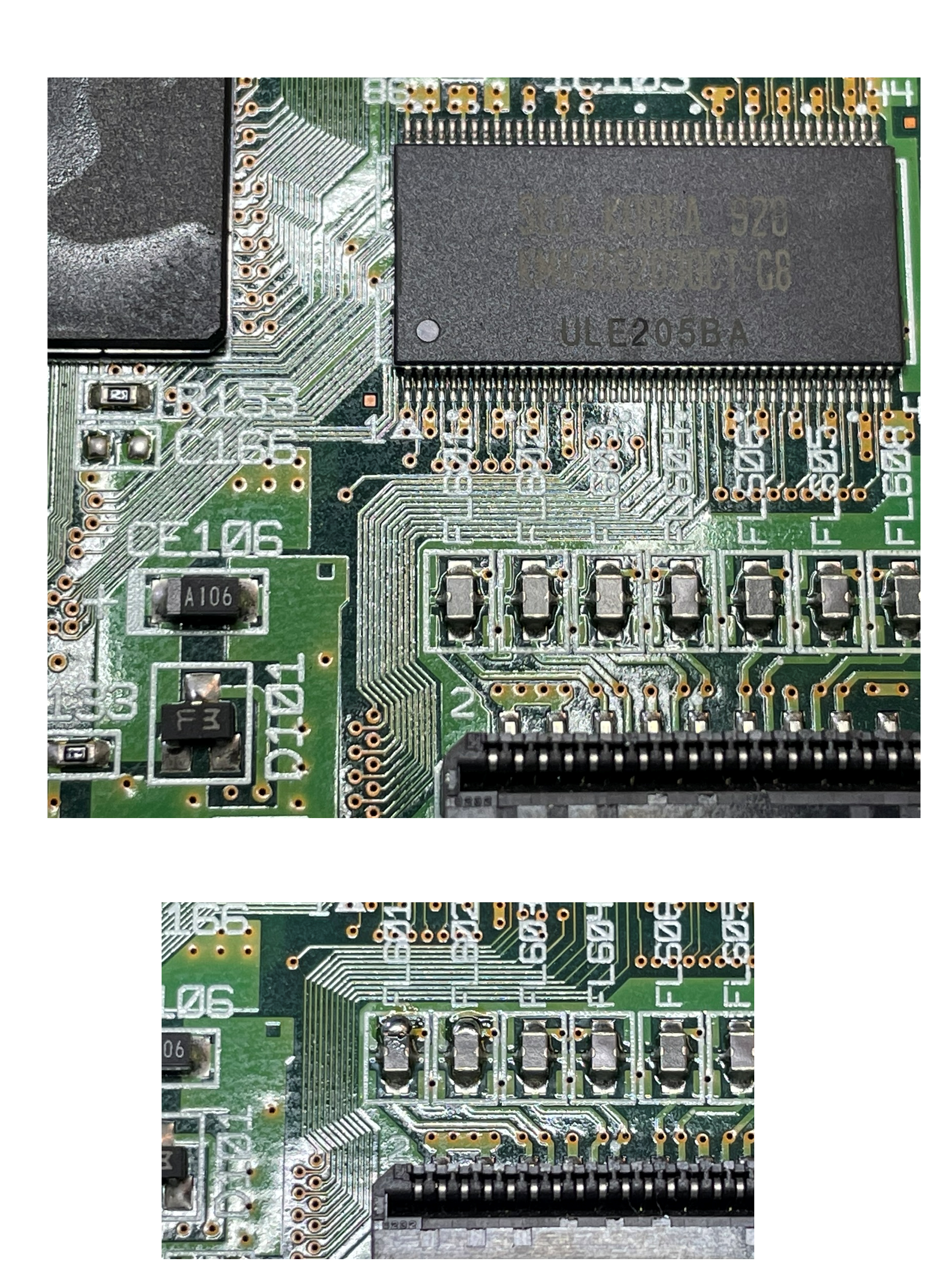
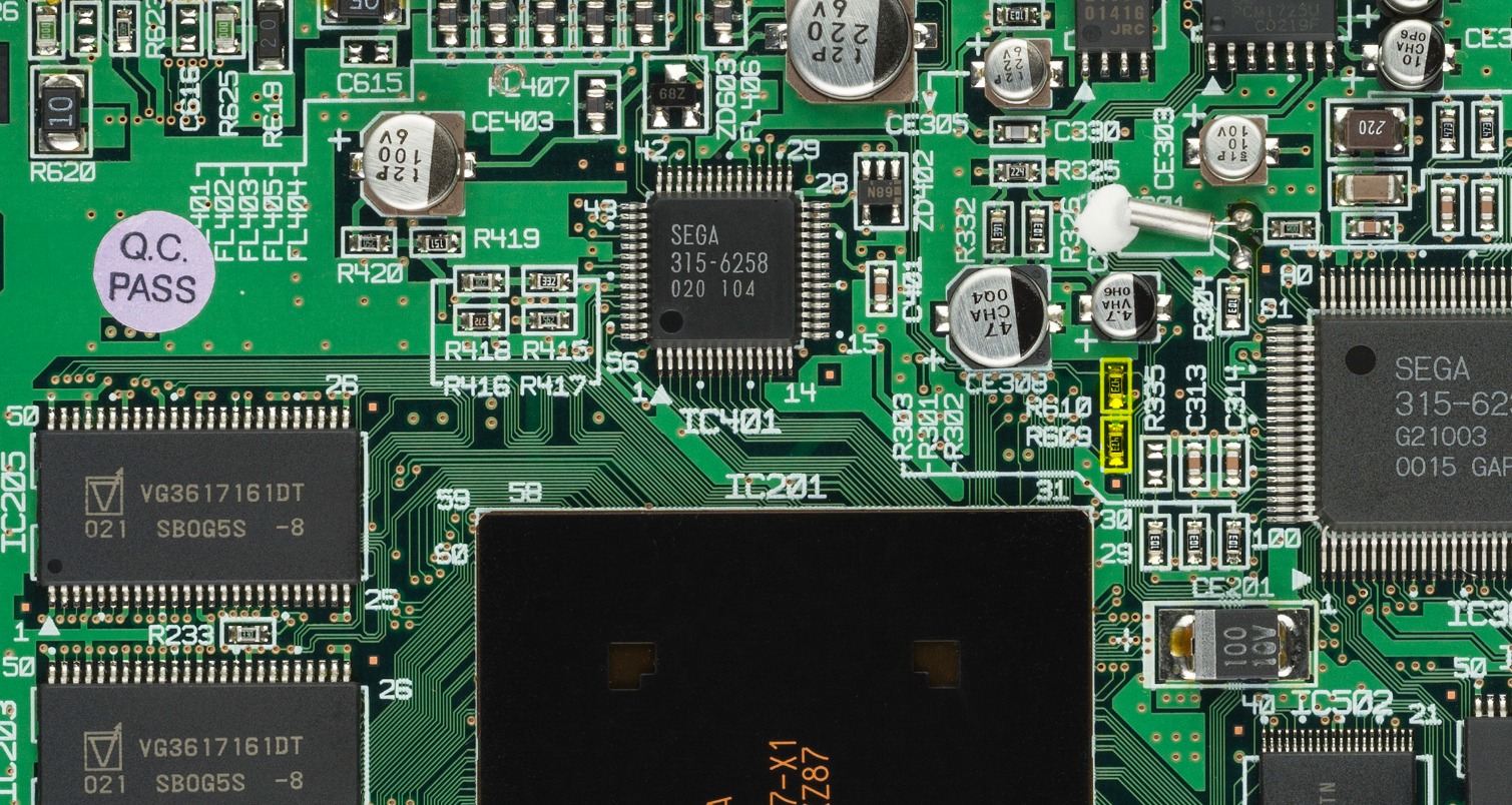
Remove R610 & R609 that are highlighted in yellow. You can discard the resistors.
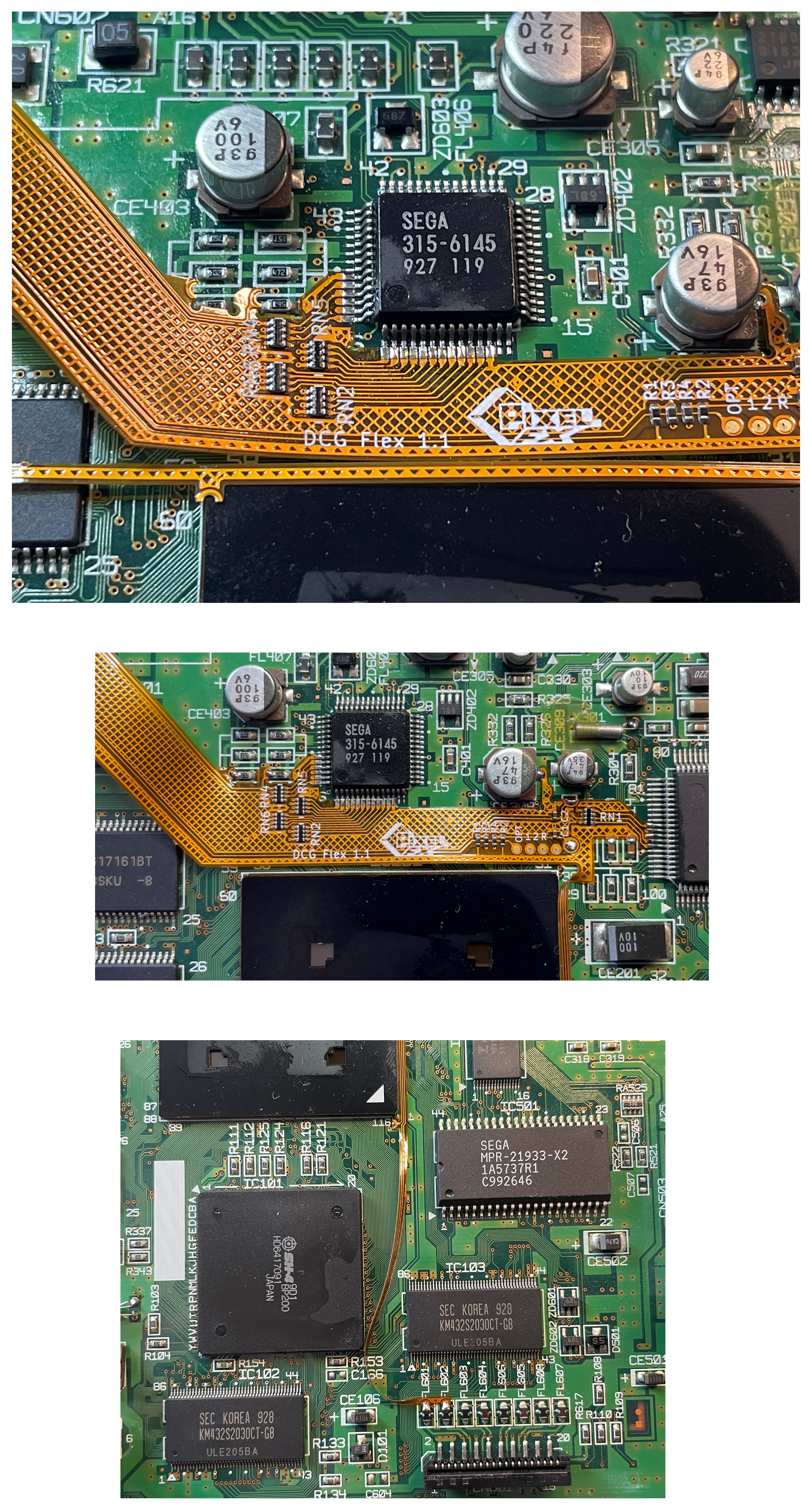
Align the flex to both sides of the DAC and tack into place. Align the other side of the flex to the audio IC and tack into place. Study the images below, make sure you are not off a pin.
Attach the GEM to the main flex as shown and install onto the bottom mount with the supplied M1.6 screws. Hint Don't crease the flex cable, just gently bend.
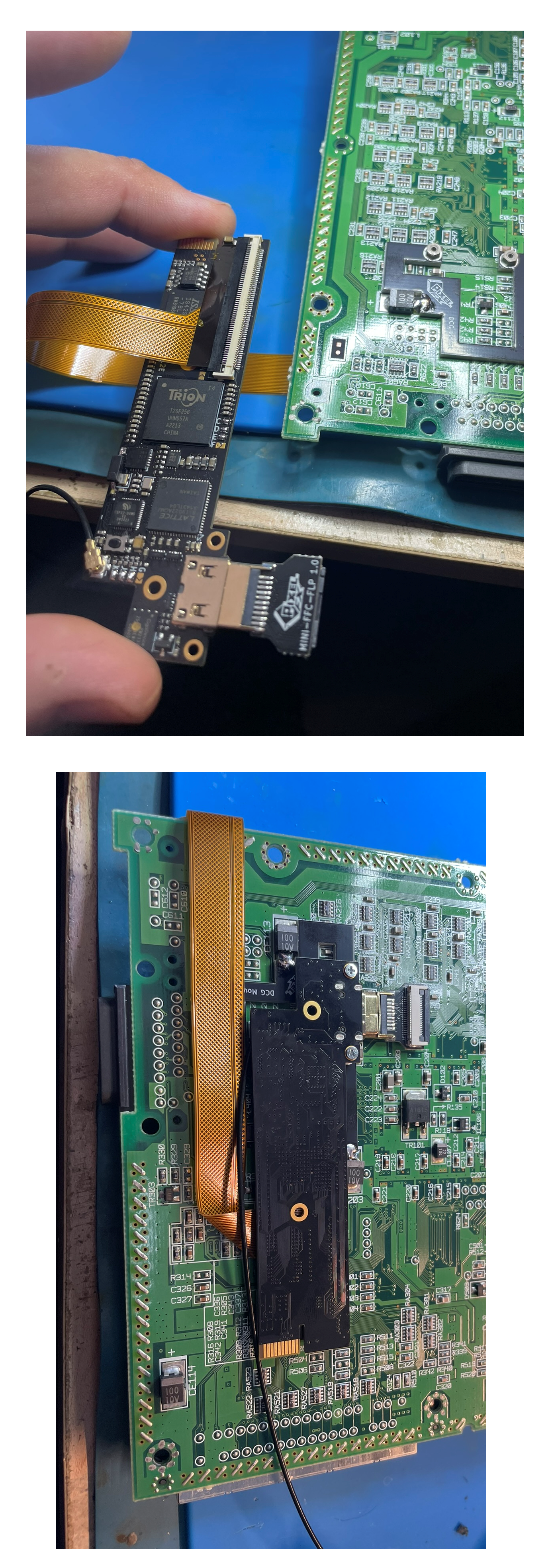
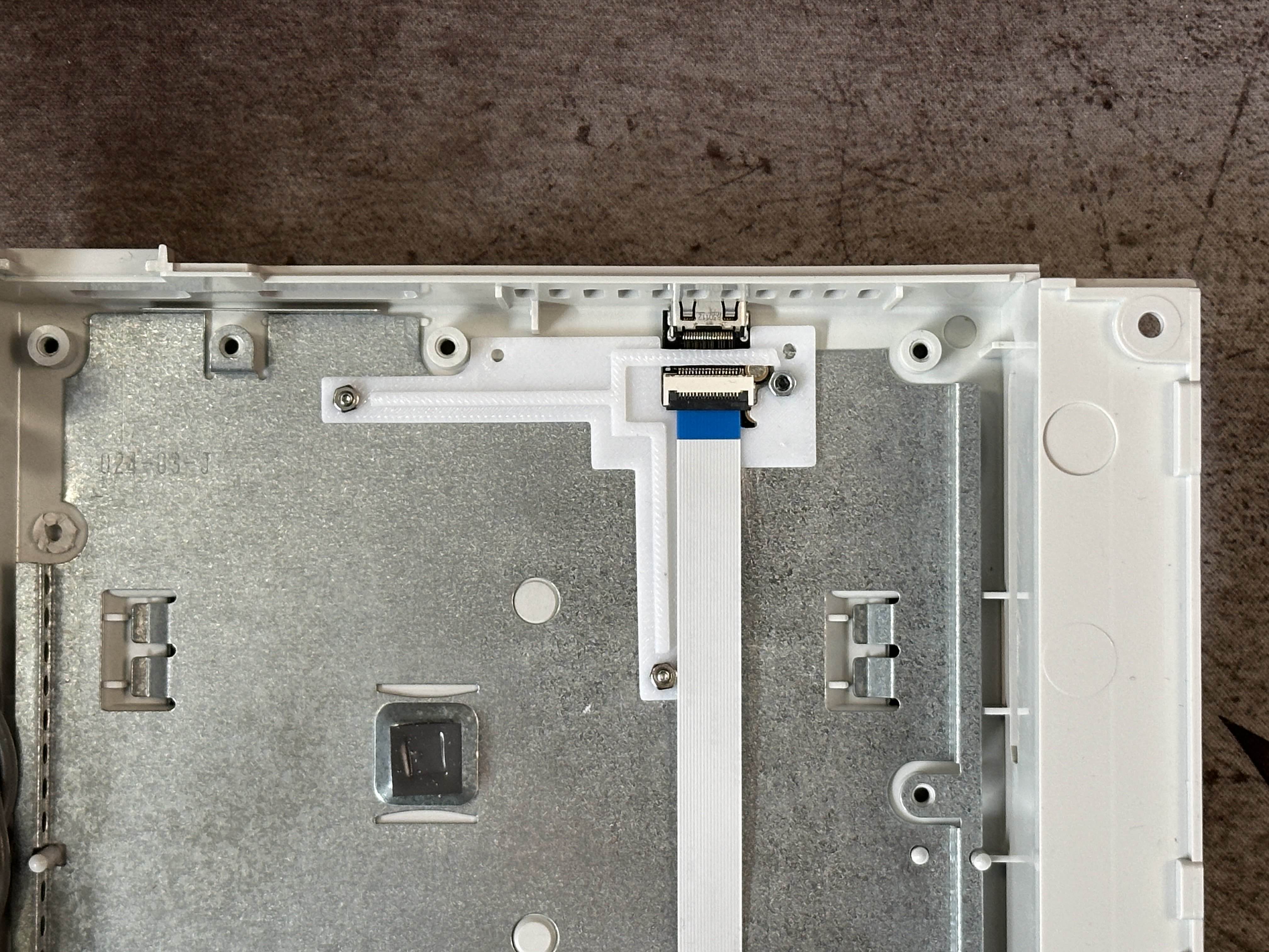
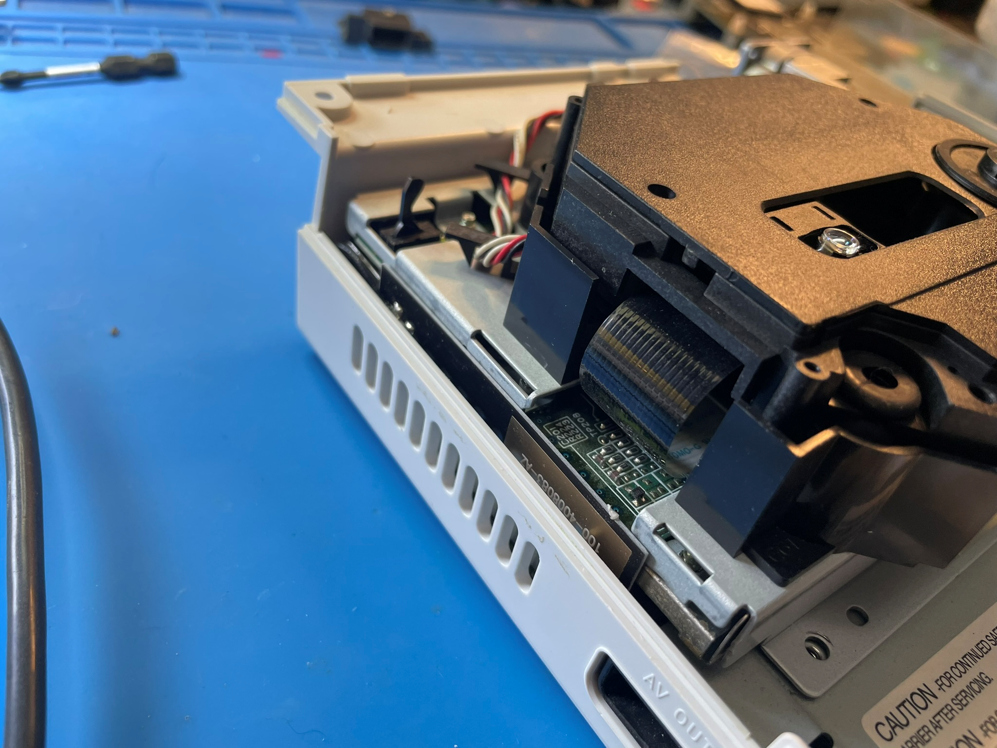
Attach the 150mm ffc cable and insert into the Dreamcast case. Route the antenna as shown. Install the Mini HDMI port on the ffc and set into place.
Re-attach the metal shield and install the antenna.
GDEMU users mount the antenna here:
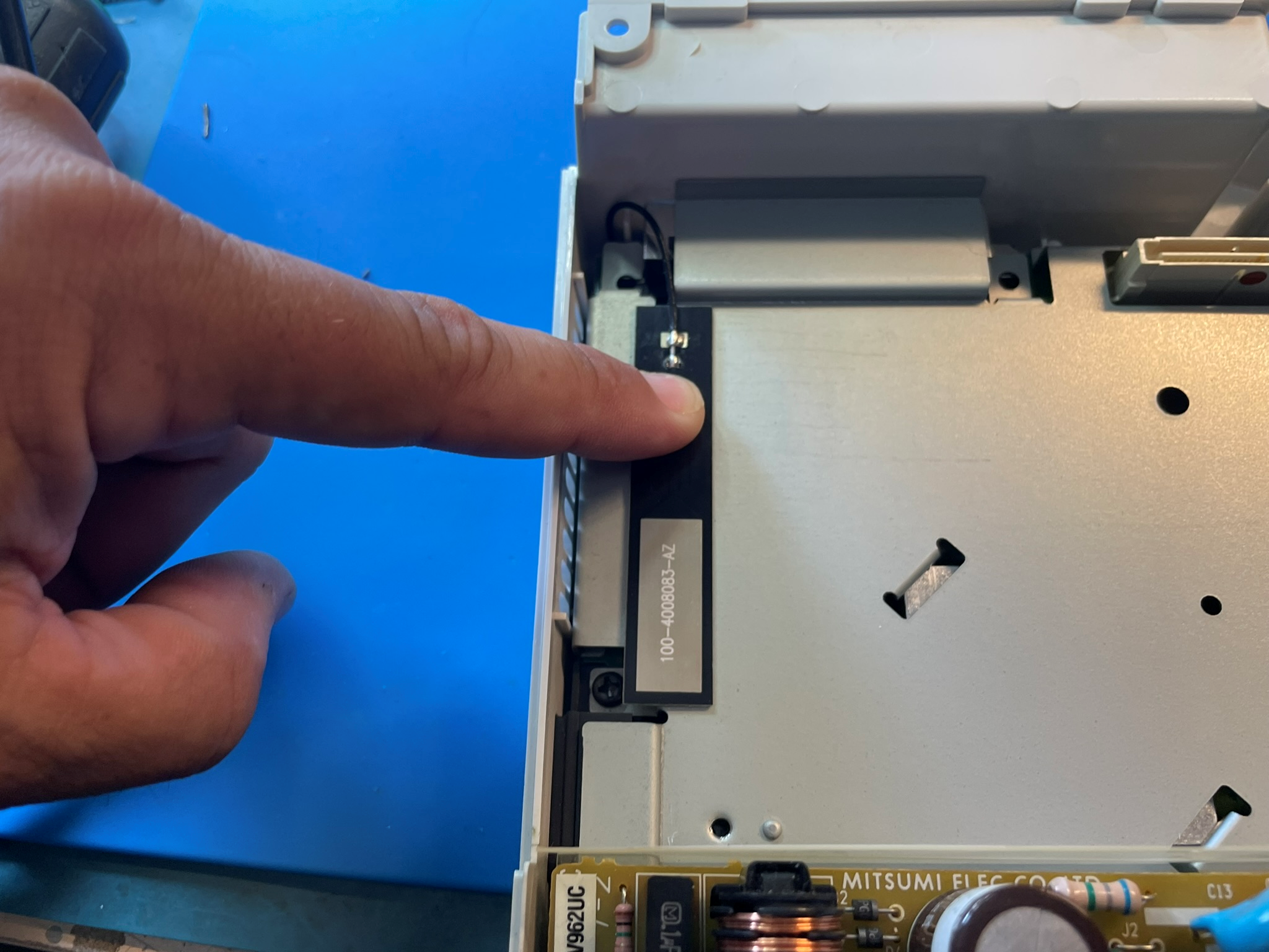
Normal GDROM users use this antenna location:
Step 3 - First Boot UP
Click to expand/collapse
With the metal shield on its safe to test the installation. There are live mains, don't forget the plastic guard! If you are powering the console without the case top installed be extremely careful. Upon first power up you should see the DC BIOS logo. If you do not, make sure your GDROM is seated properly. This can cause weird no video situations sometimes.
Open up the OSD by using L + R + DPad R + B
By default, the GEM is in a cable detect state (15khz 480i). To force 480p progressive mode without a VGA box connected, open up the OSD and go to System -> DCDigital Settings.
Verify all your pins showing hearts in the debug menu. System -> Debug
For pinout information please visit this page: https://docs.pixelfx.co/GEM-Pinouts.html
If you made it congratulations! This is no easy feat and you should be proud.

Step 4 - Optional Pin Control (USB-GDROM, MODE, GDEMU)
Click to expand/collapse
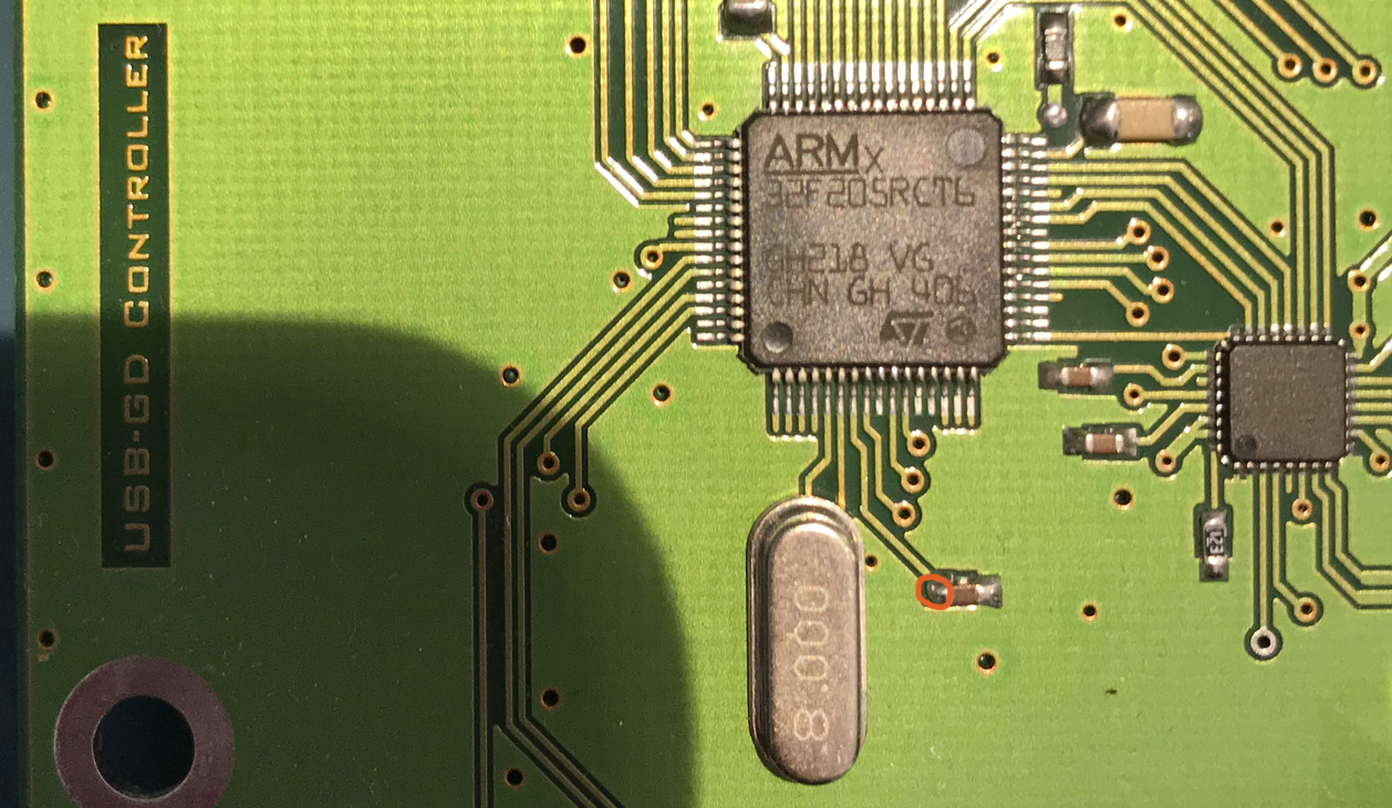
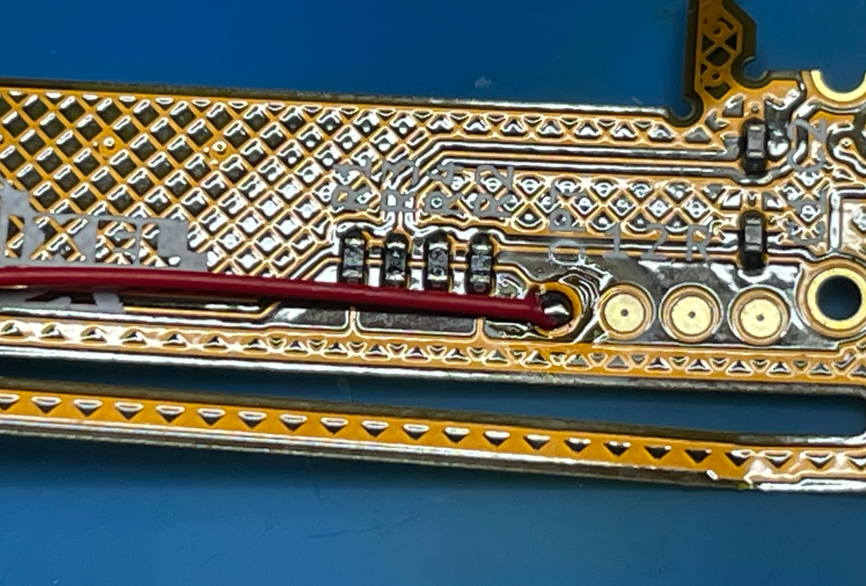
The optional pad location is found on top side of the flex. Labeled OPT. Only use 30 AWG solid core wire for this connection. Otherwise the pad will likely tear off.
The settings of the optional pin can be found in the OSD System -> DCDigital Settings. The optional pin can cause no boot situtions to occur if set to the wrong setting. Be careful when apply settings.
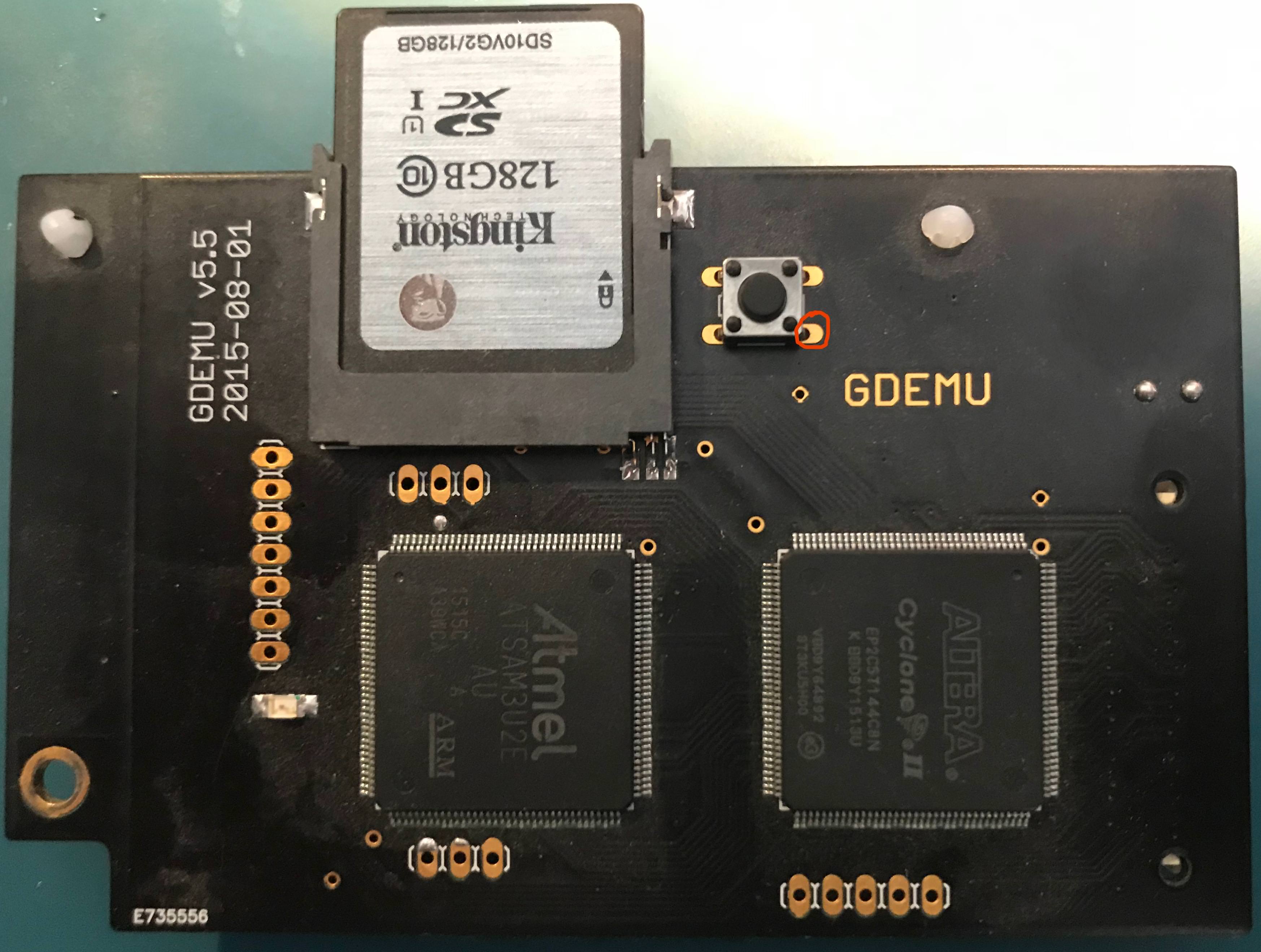
GDEMU Hookup:
USB-GDROM Hookup: