DCDigital HW2 Installation Instructions
Disclaimer:
This kit is for advanced installers only. Install at your own risk. We cannot be held responsible for damage to your console and/or kit. Each kit is individually tested and confirmed working before being shipped out.
2.1.17 Firmware Bug
The launch firmware included with the first batch of kits must be updated to the latest stable (2.1.23 or higher) before switching the output to "Force VGA" in the Dreamcast settings of the OSD. Without doing so can cause a softbrick in which the unit might need to be updated through the rescue system.
Before you begin:
DCDigital is compatible with all DC models/regions.
The guide will not go over the tear down of the dreamcast. There are many guides online that cover this.
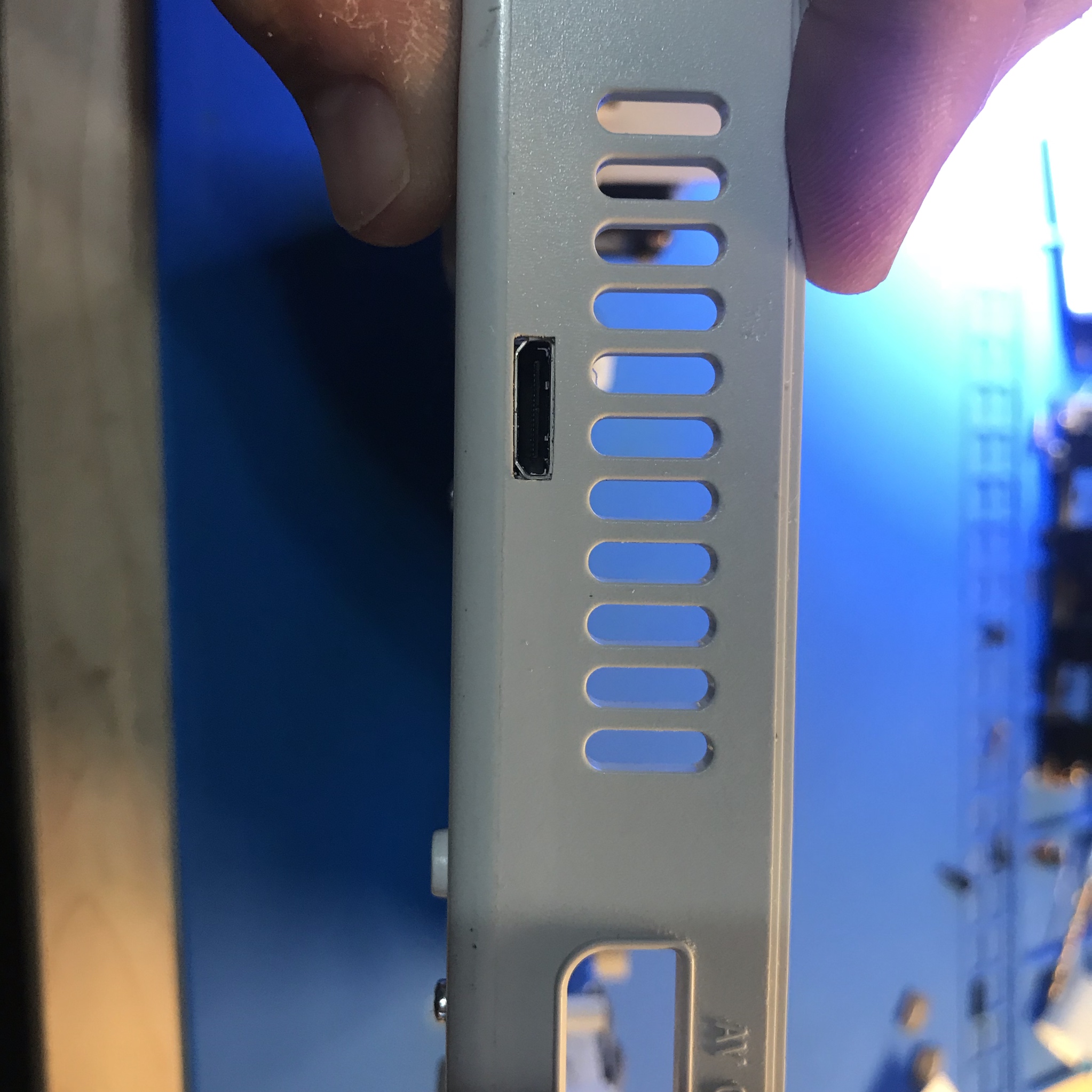
The DCDigital requires a small case cut for the mini HDMI connector.
Kit includes:
- DCDigital PCB
- Main Flex
- Controller Flex
- Drill alignment tool
- Vinyl backing
Items required
- Temperature Controlled Soldering Iron
- Leaded Solder
- Non Corrosive, No Clean Flux (I recommend Kester 959T)
- 99% Isopropyl Alcohol
- Side Cutters
- Multi Meter
- Miniature File Set & Exacto Knife (Cut Version)
- P1 & P2 Screwdrivers
- 2.3mm (or similar) drill bit
- 1.5mm drill bit (opitional)
Step 1 - Install vinyl backing
Click to expand/collapse
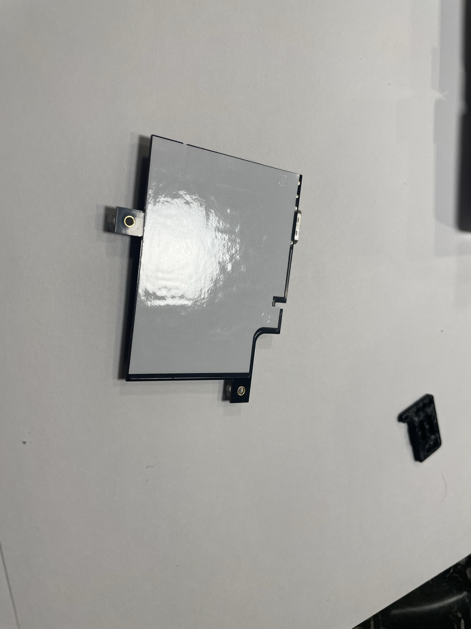
Peel off the paper layer of the vinyl backing and apply it to the back of the DCDigital pcb.
Step 2 - Mounting the HDMI board
Click to expand/collapse
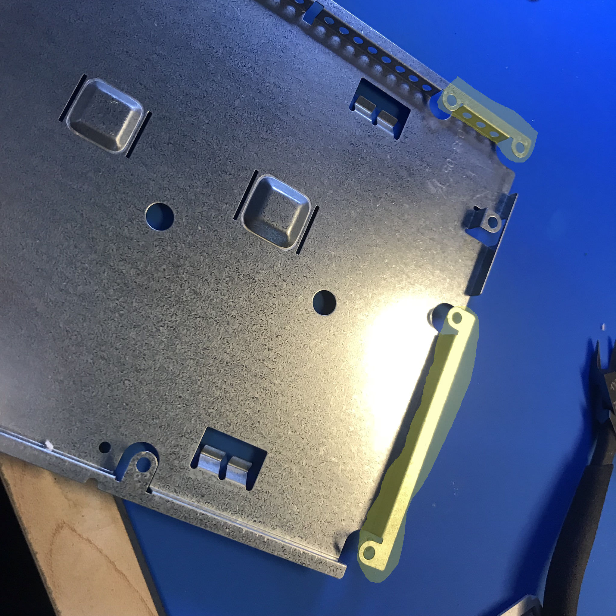
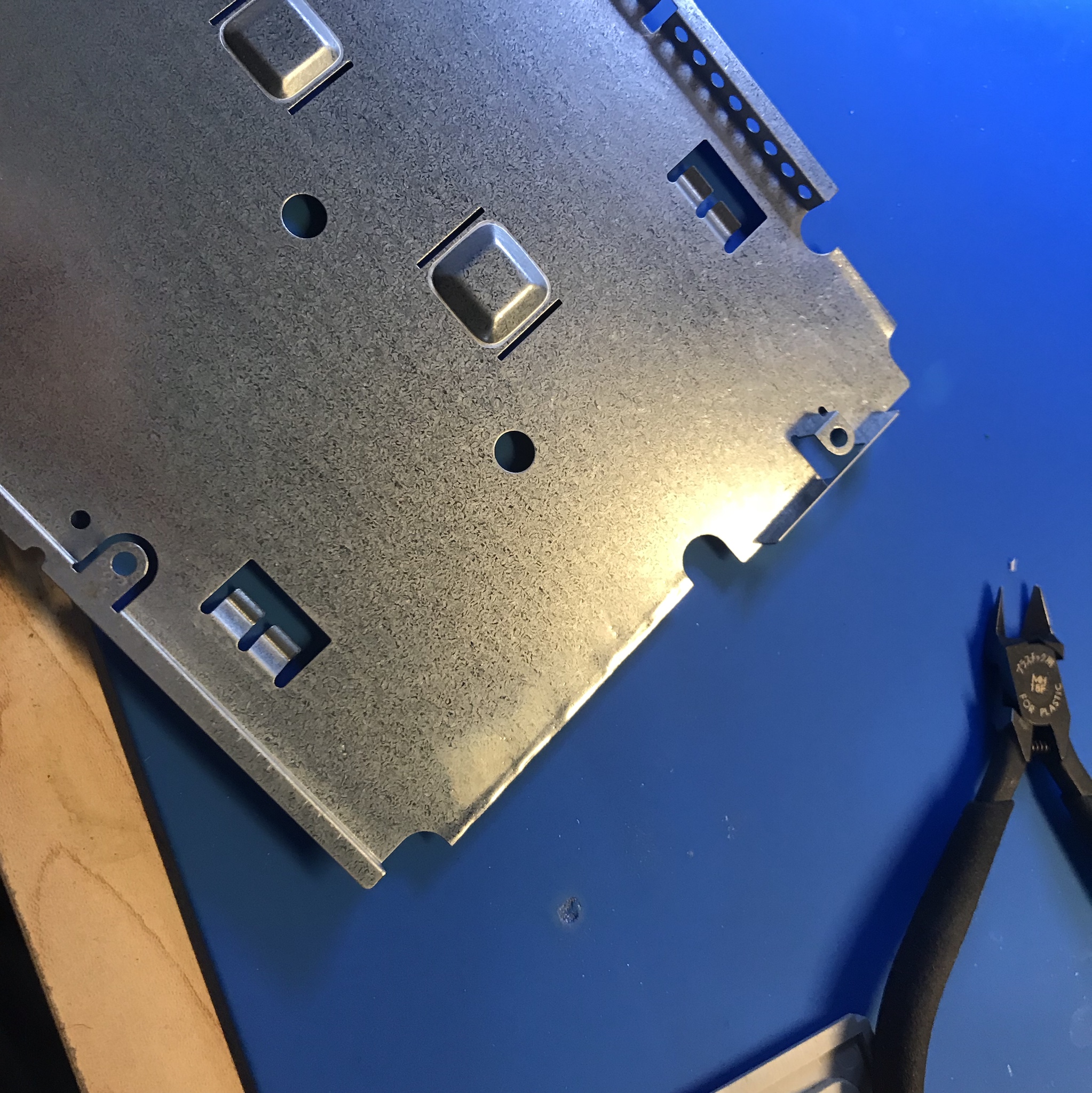
Disassemble the Dreamcast, so the motherboard is free. *Keep track of the thermal pads, there are some on top and bottom of the motherboard. Use side cutters and pliers (Bend metal back and forth until is snaps off cleanly) to remove the follow areas highligted in yellow.
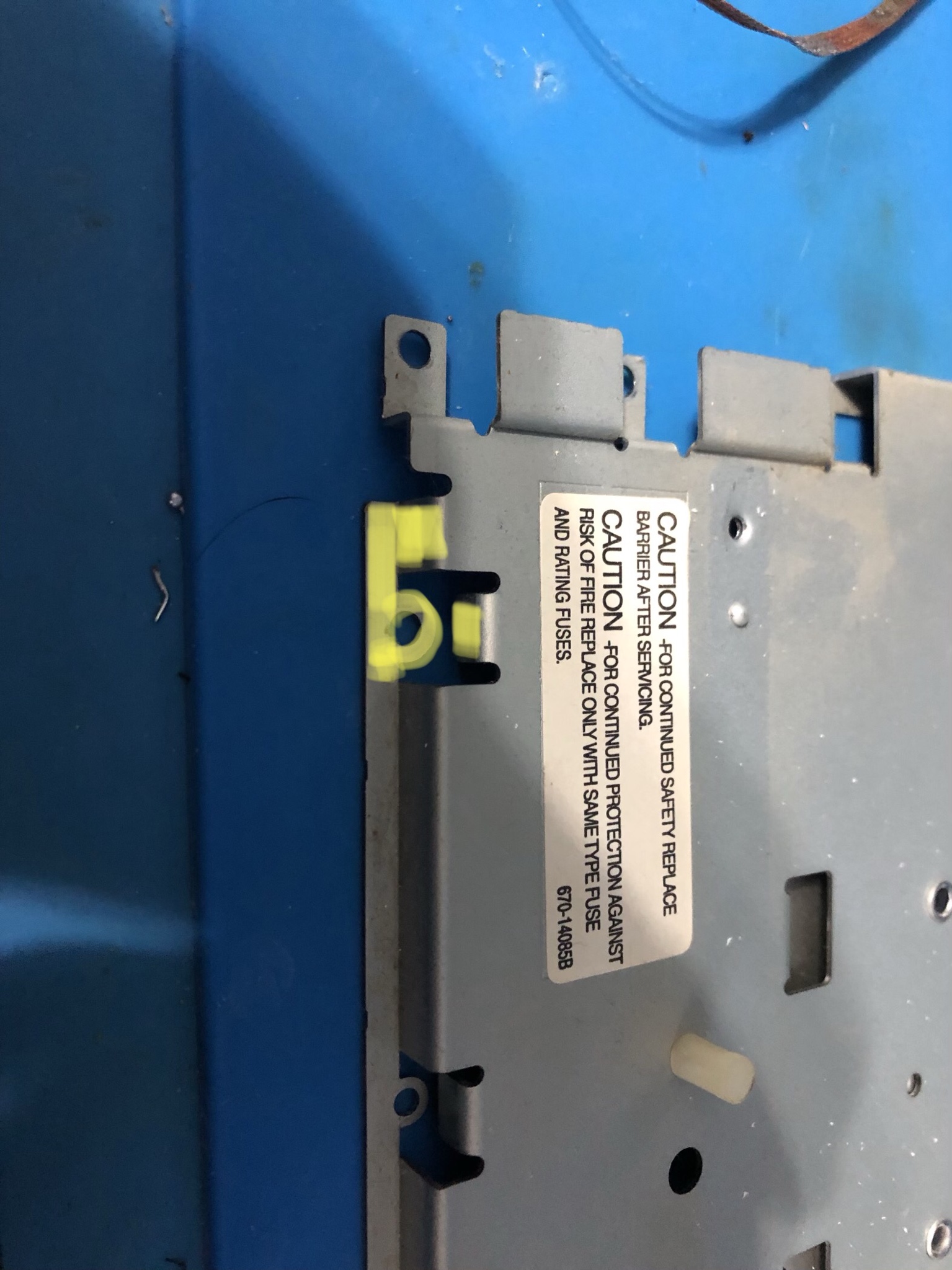
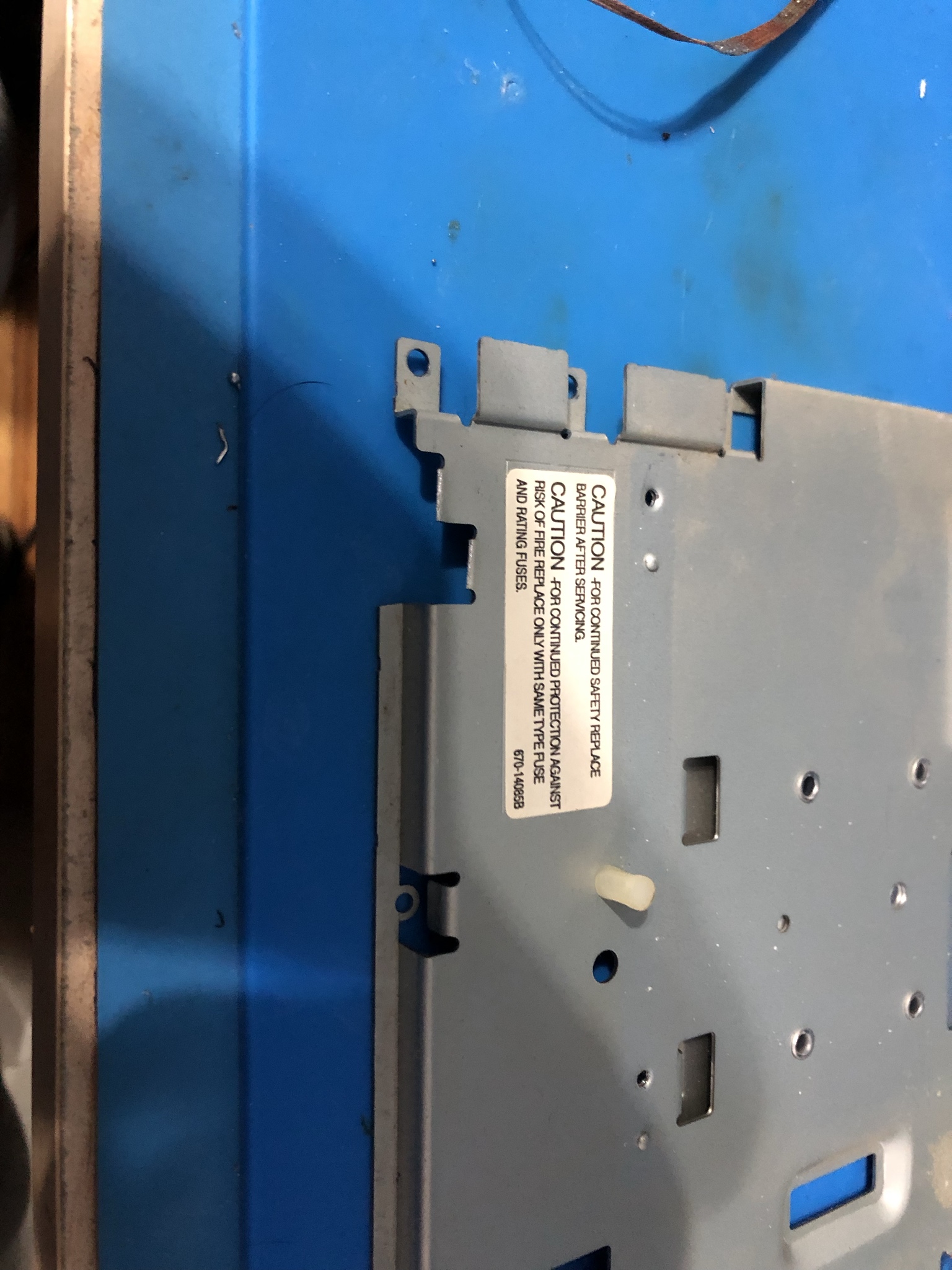
Use scissors and remove the material highlighted in yellow. This material is thinner, and cuts easily.
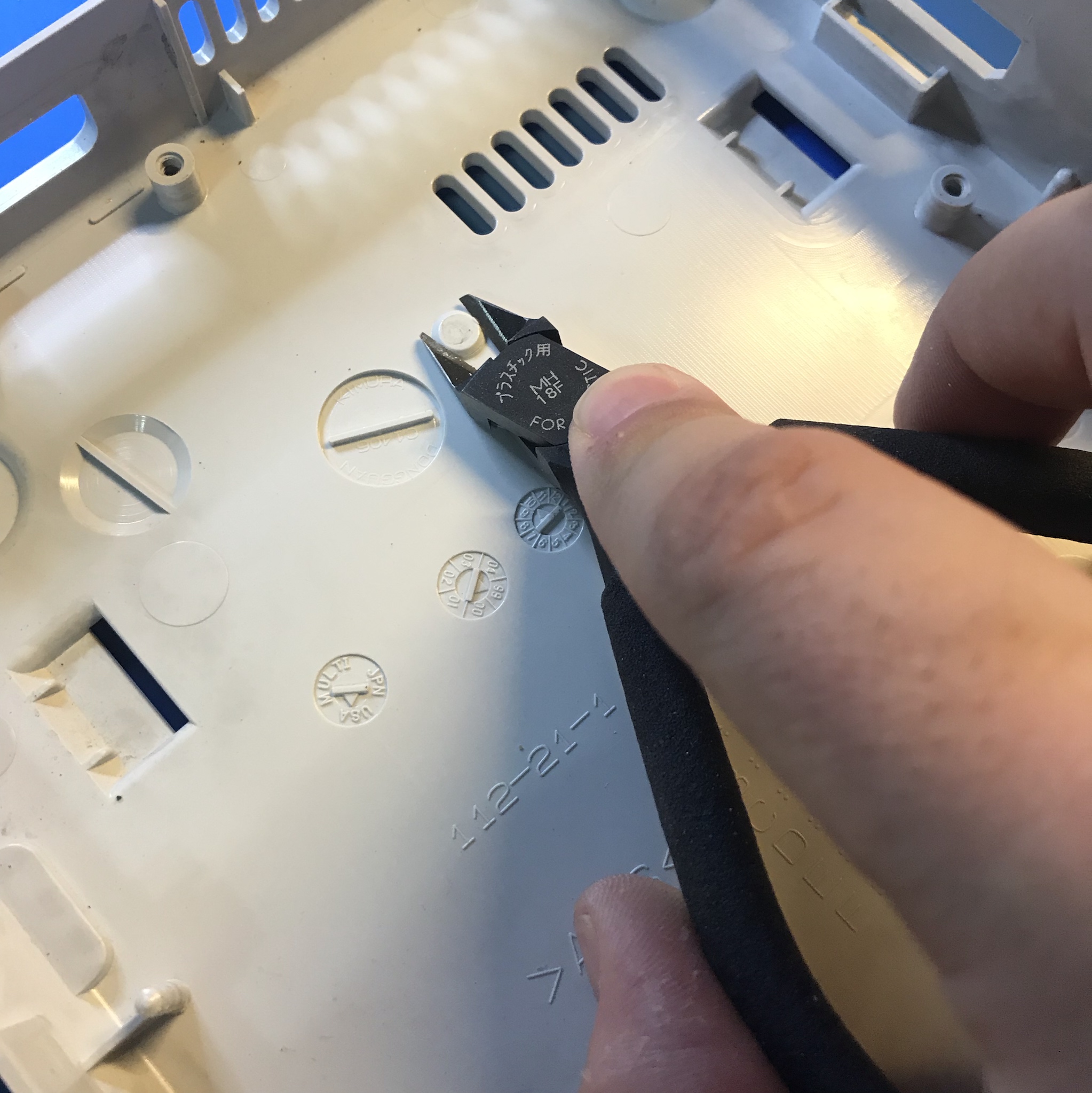
Cut off the plastic screw boss with side cutters
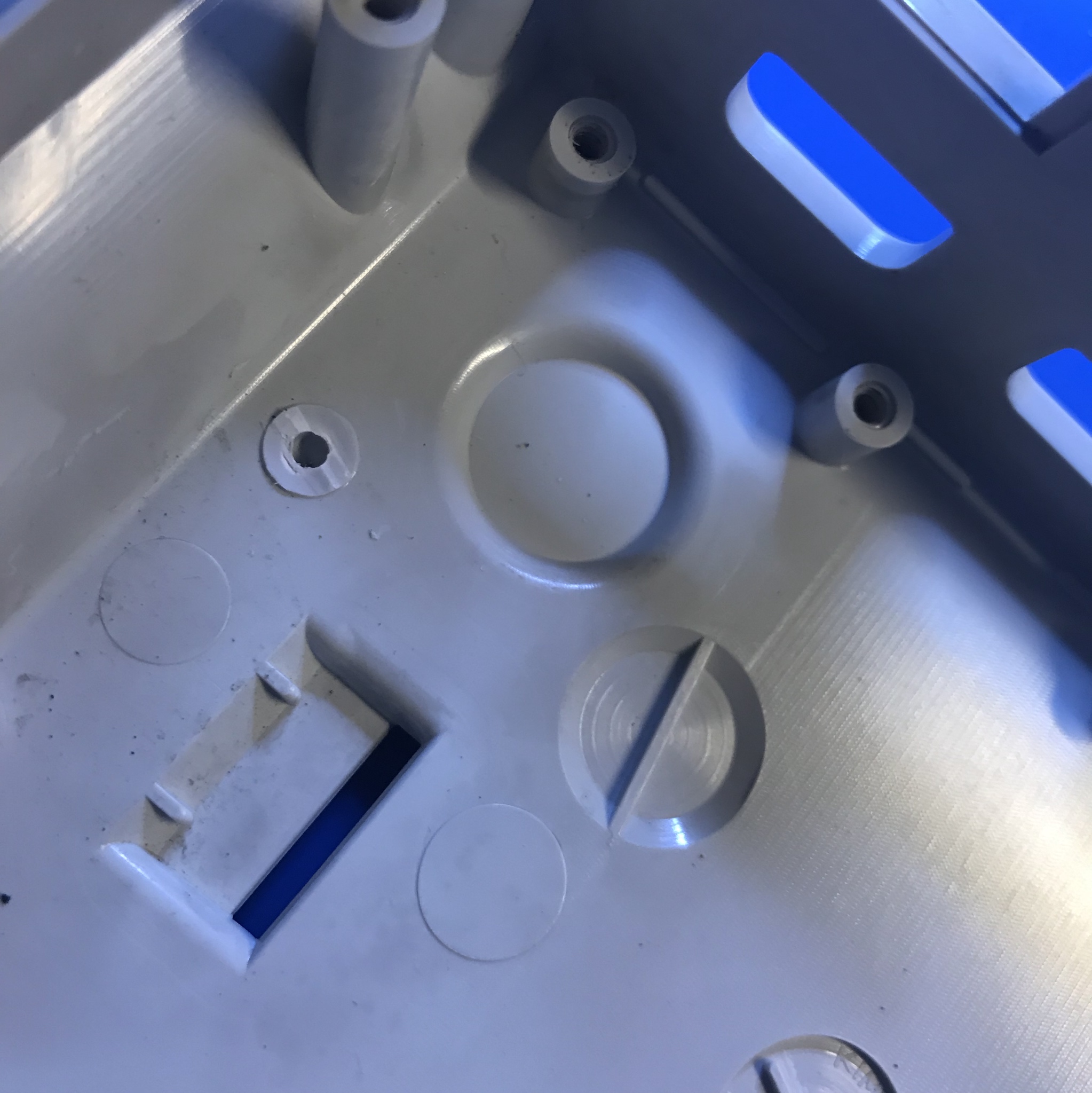
Some consoles have this plastic nub. If yours does remove it with side cutters.
Insert the drill blog jig exactly as shown below.
Drill out the 3 holes and then flip it 180 to drill the two other holes.
Optionally drill out the rescue button hole with a 1.5mm drill bit

Use the small square and flat files and square the hole up. DO NOT make the hole larger than what the drill bit did. We are just squaring the hole.
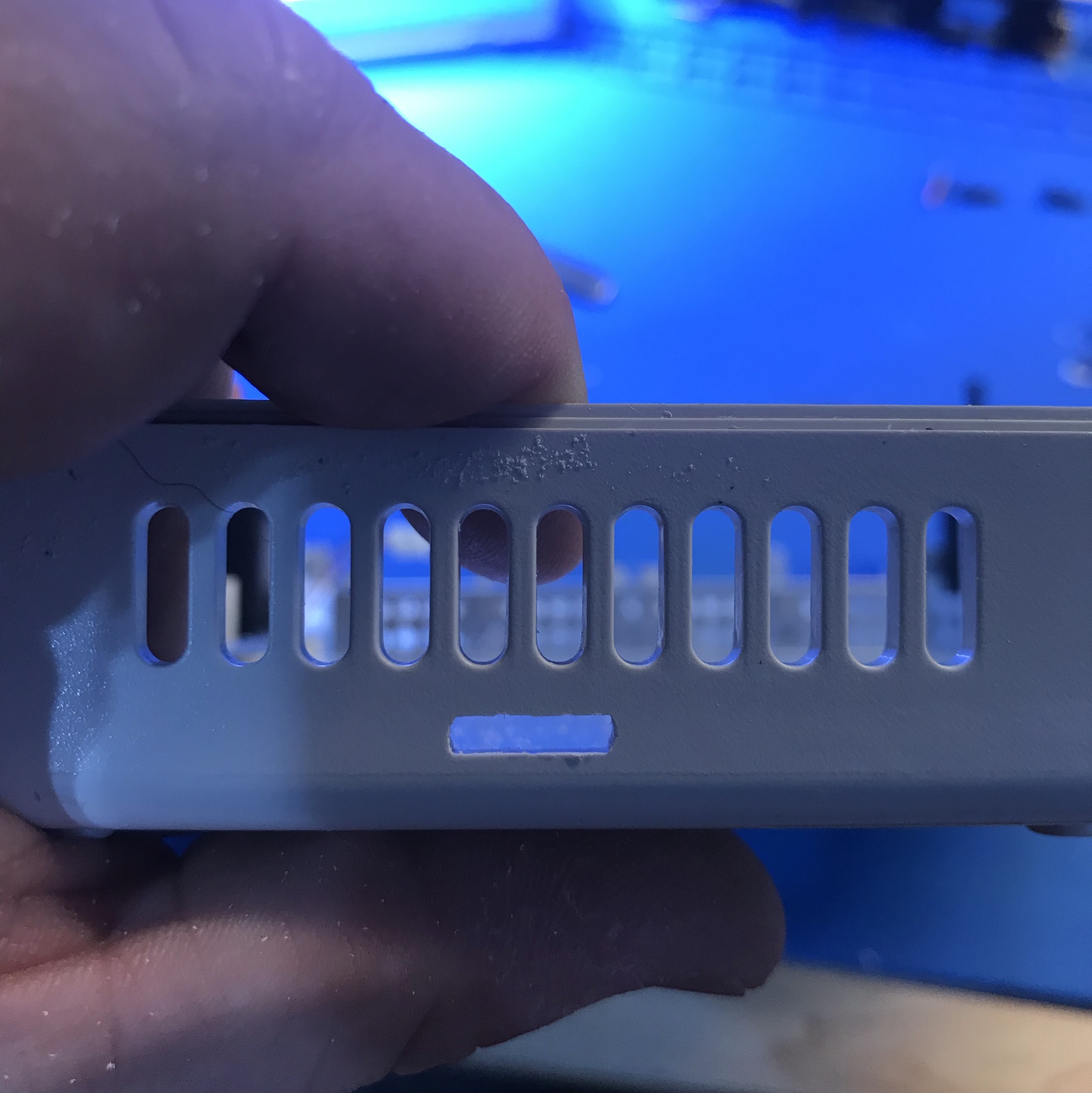
Slowly file, only removing a little bit of material. Then check for fitment (Make sure bottom metal shield is in place. Repeat these steps until the board can slide in firmly and lay flat.
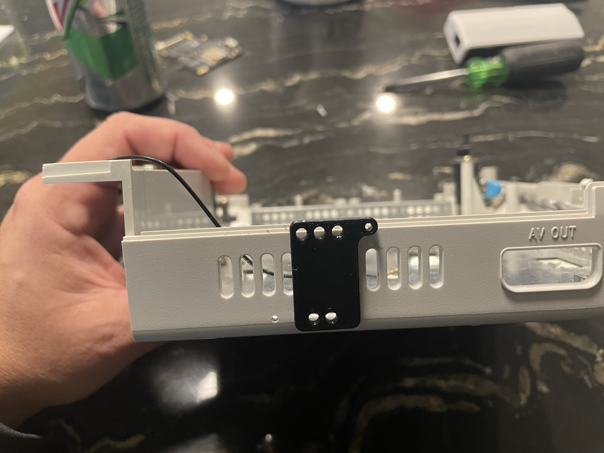
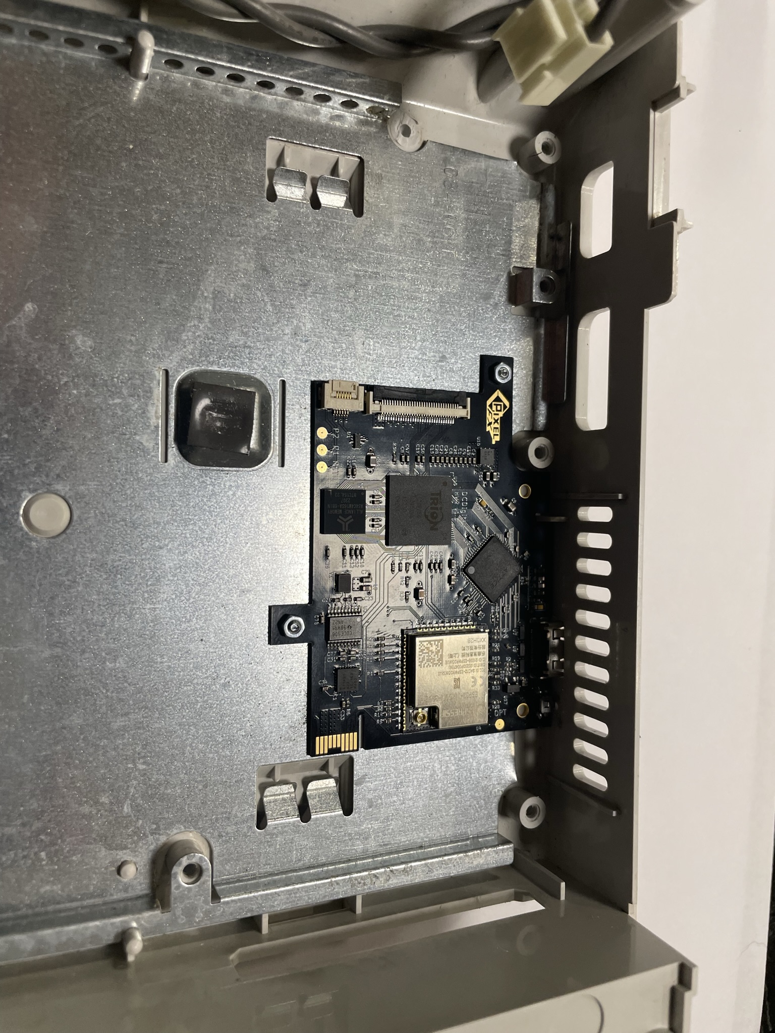
Drill two small holes, using the PCB as a guide and mount PCB with supplied M2 screws and nuts. Tip, drill 1 hole and mount screw. Then drill the other hole and mount screw.
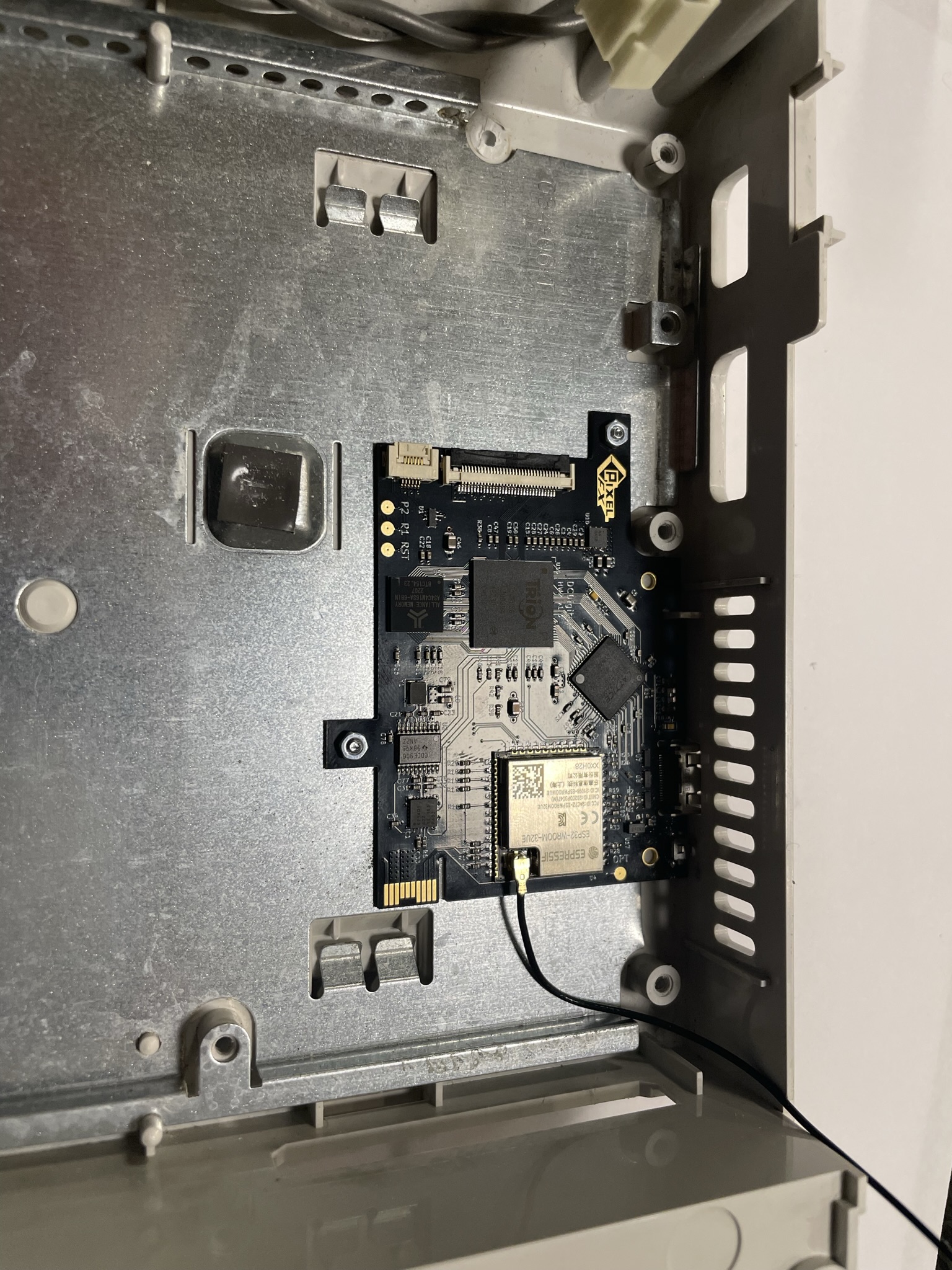
Install the provided Antenna, and route to the edge.
Step 3 - Soldering the main flex
Click to expand/collapse
Remove R610 & R609 that are highlighted in yellow. You can discard the resistors.
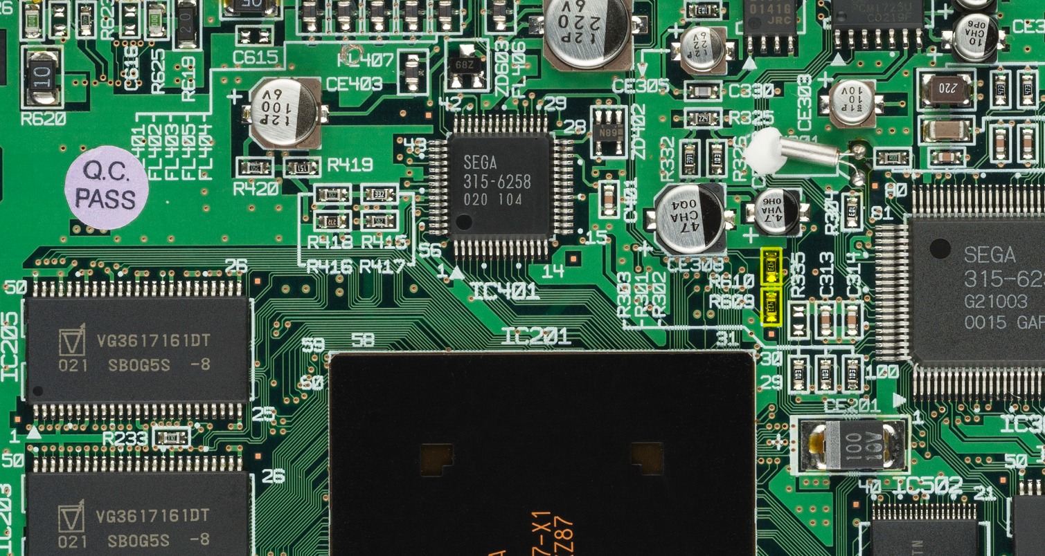
Remove Excess solder from pads R610 & R609 with desolder braid Some motherboards have R335 populated, and some don't. This is normal, do not remove it.
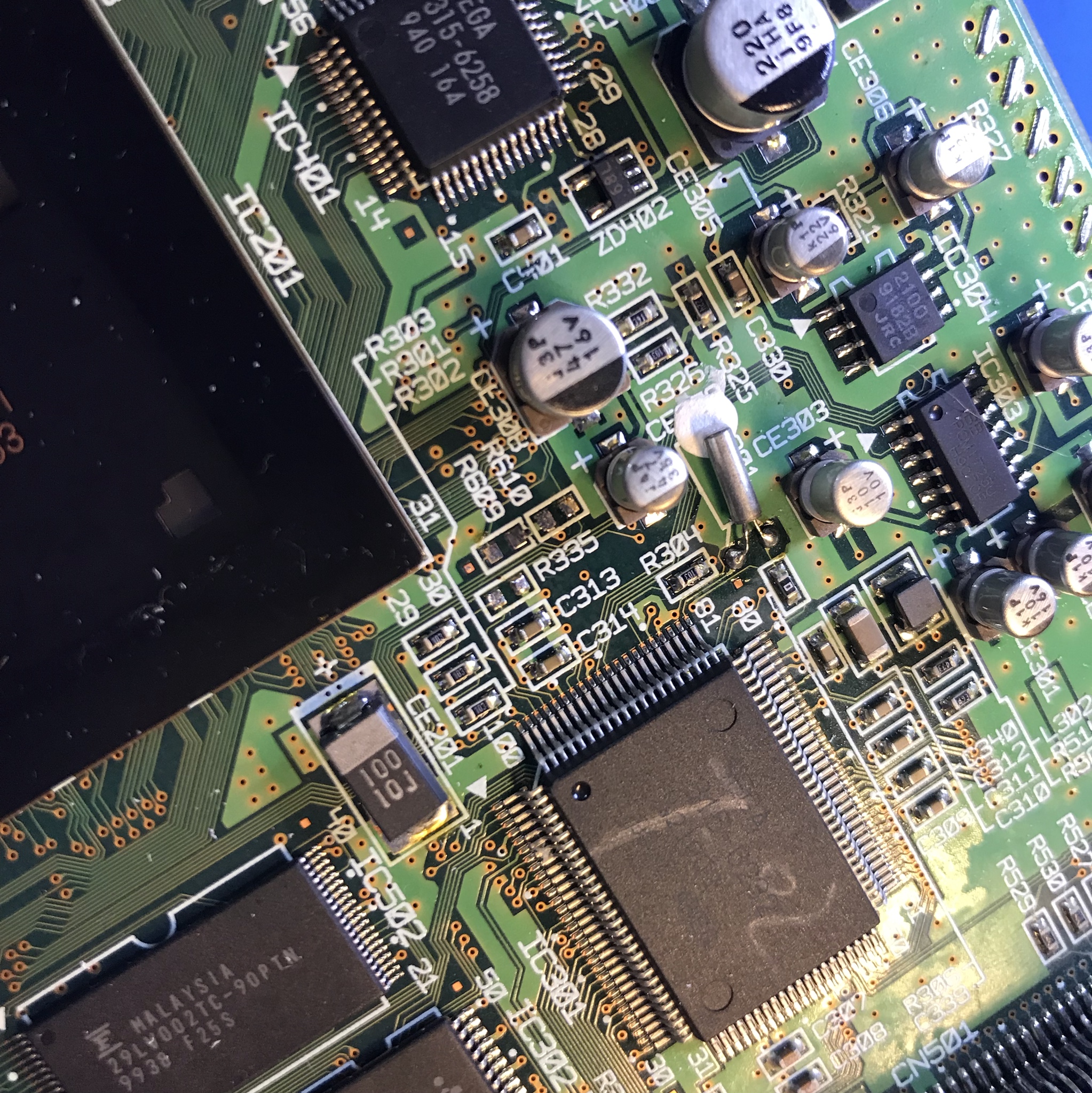
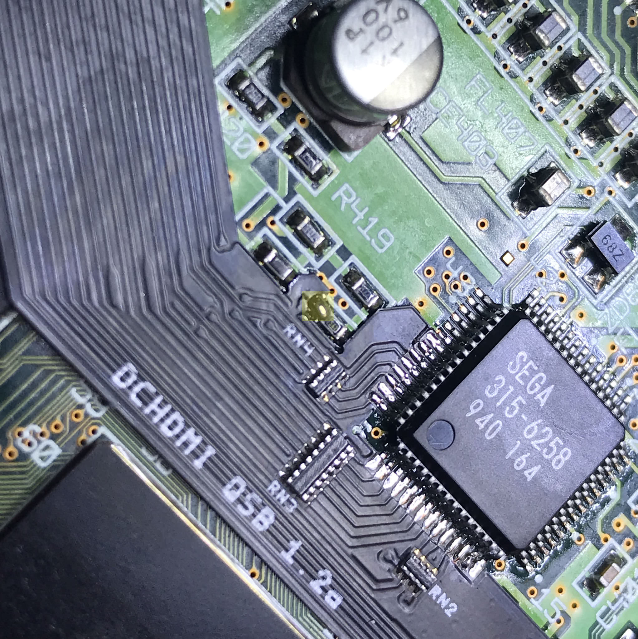
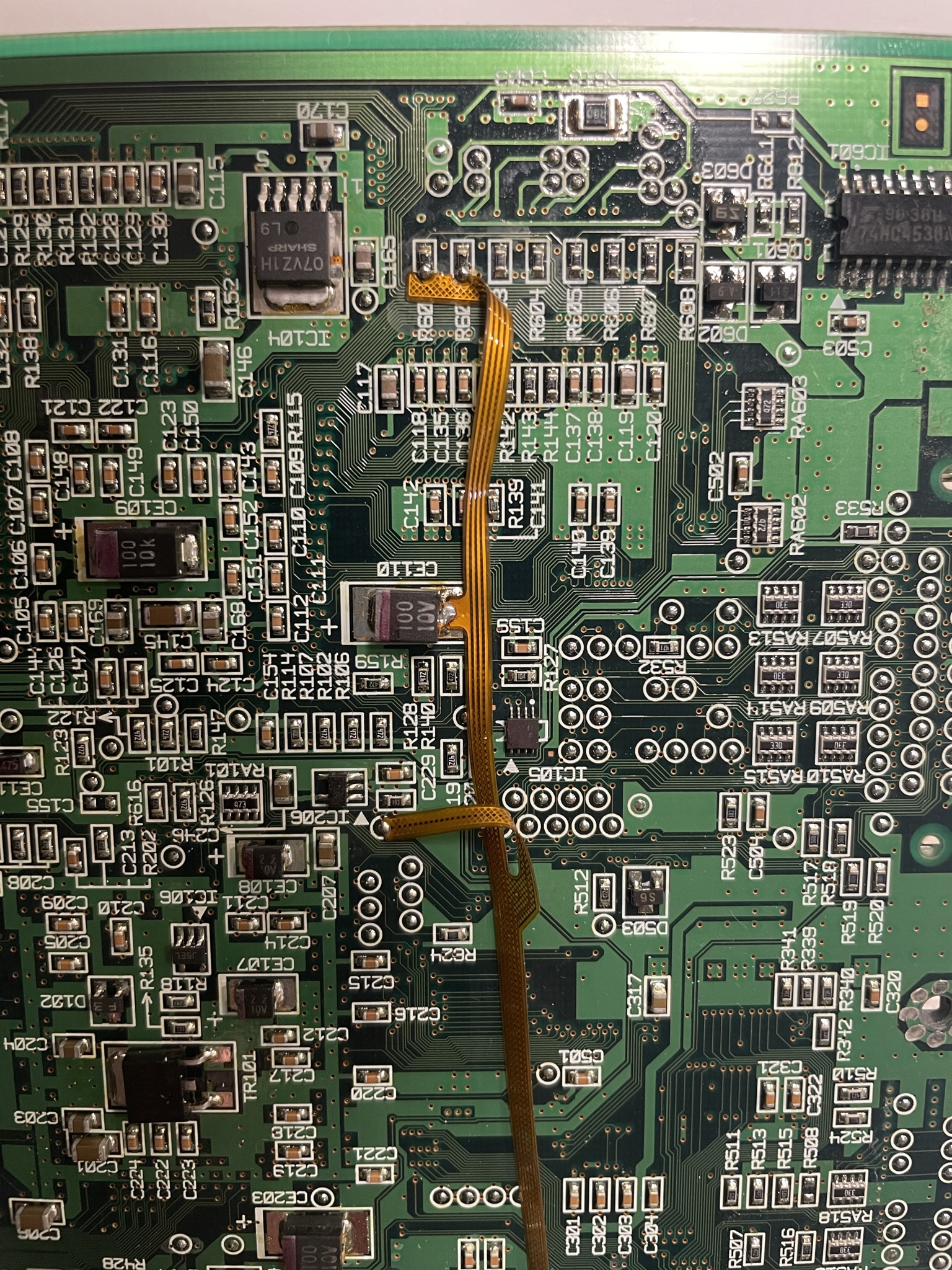
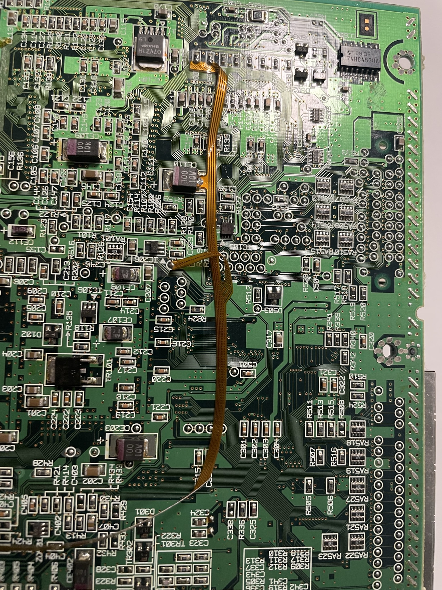
Align Flat flex on with Audio IC and tack into place
Align Flat flex with the video DAC and tack into place

Solder the rest of the flat flex into place
Solder all the areas highlighted in yellow to the flex & motherboard.
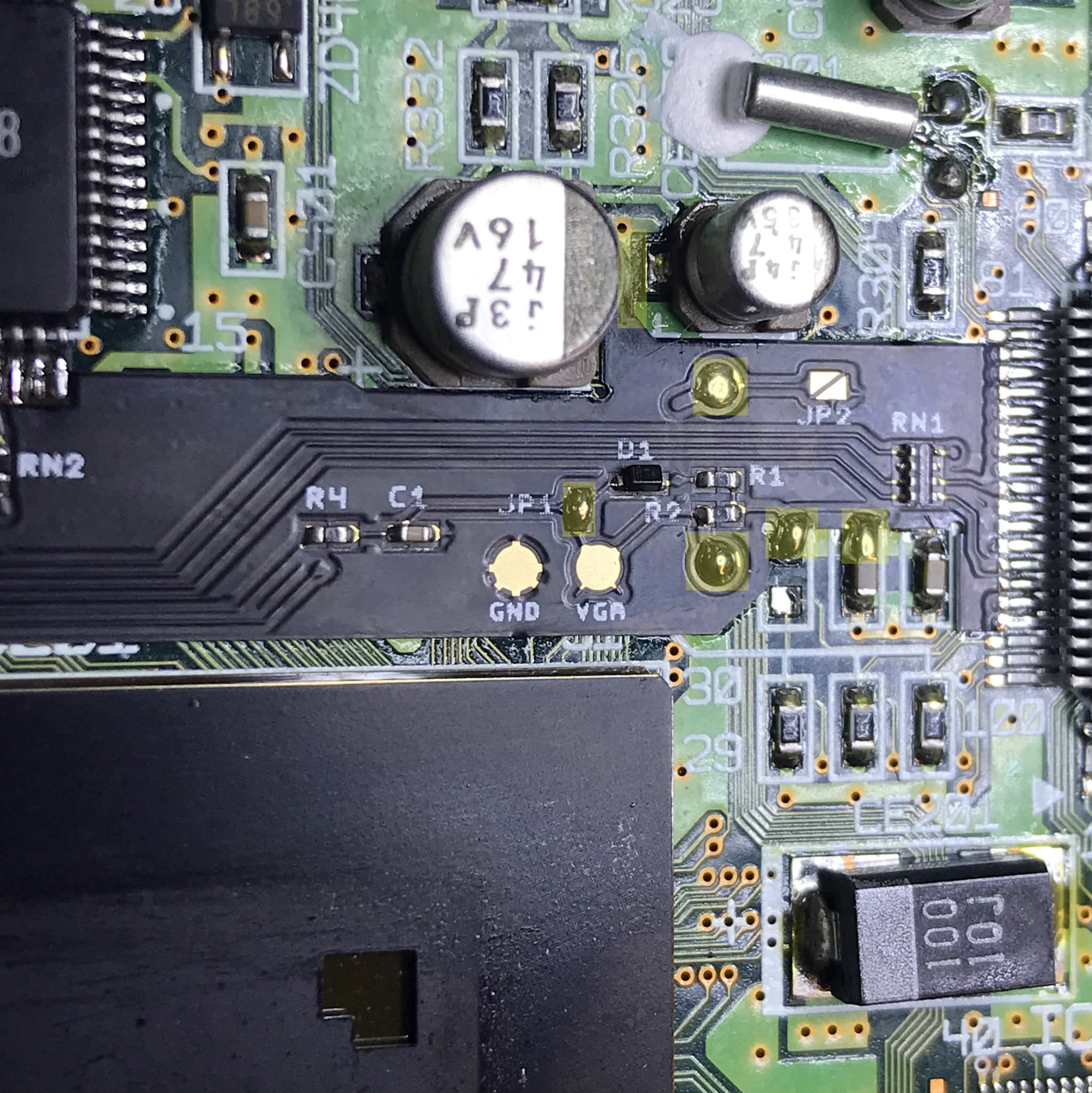
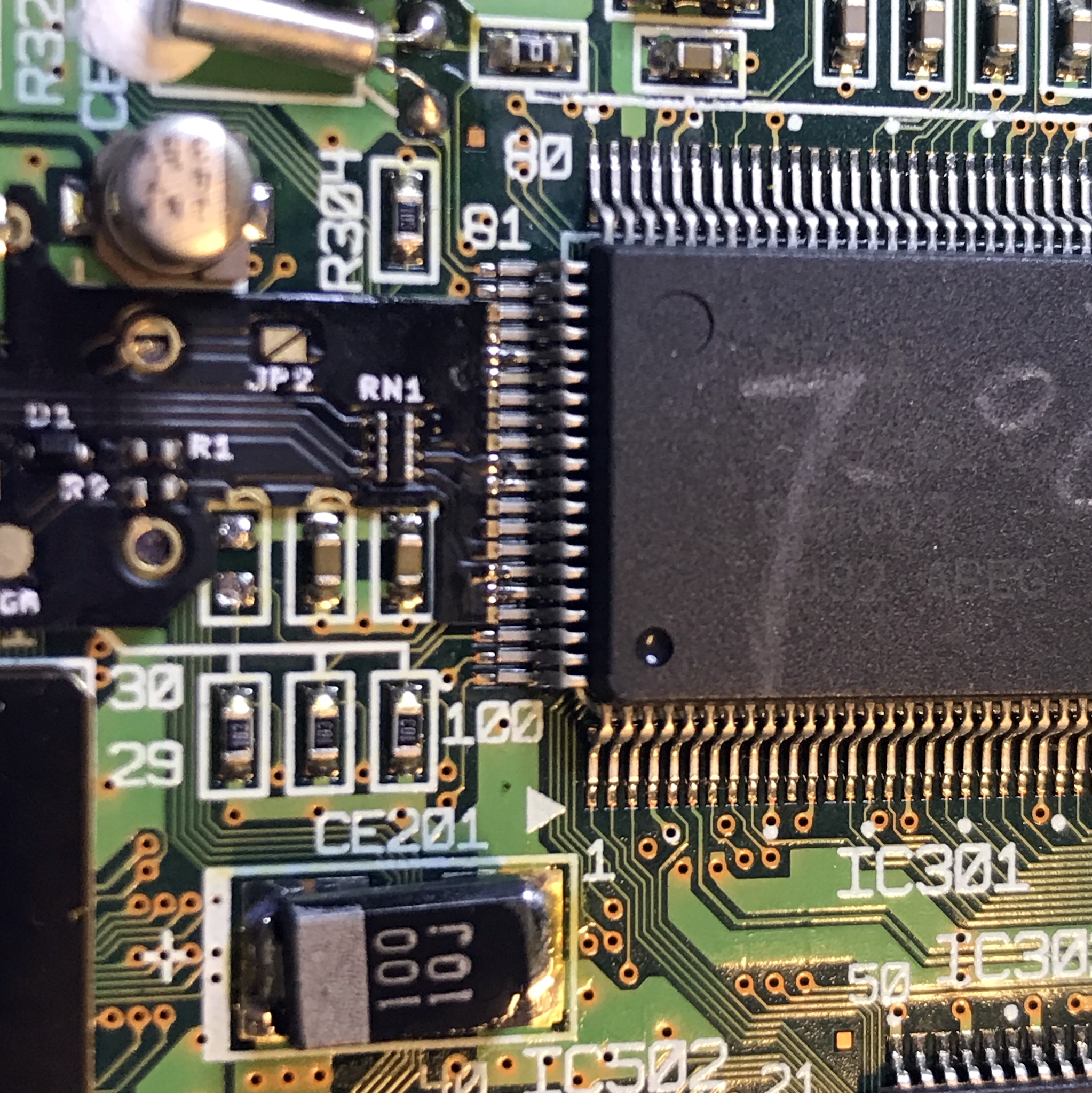
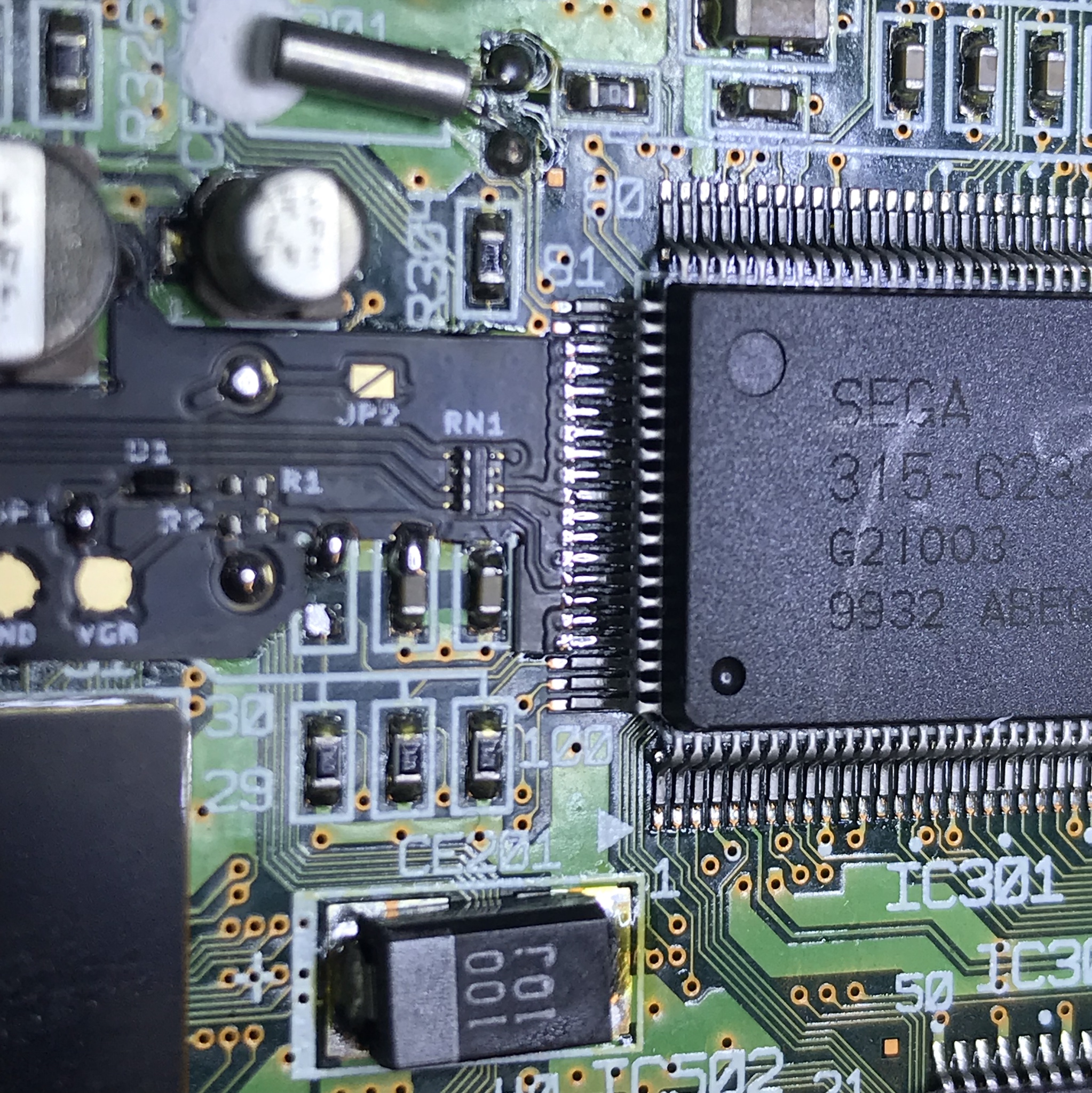
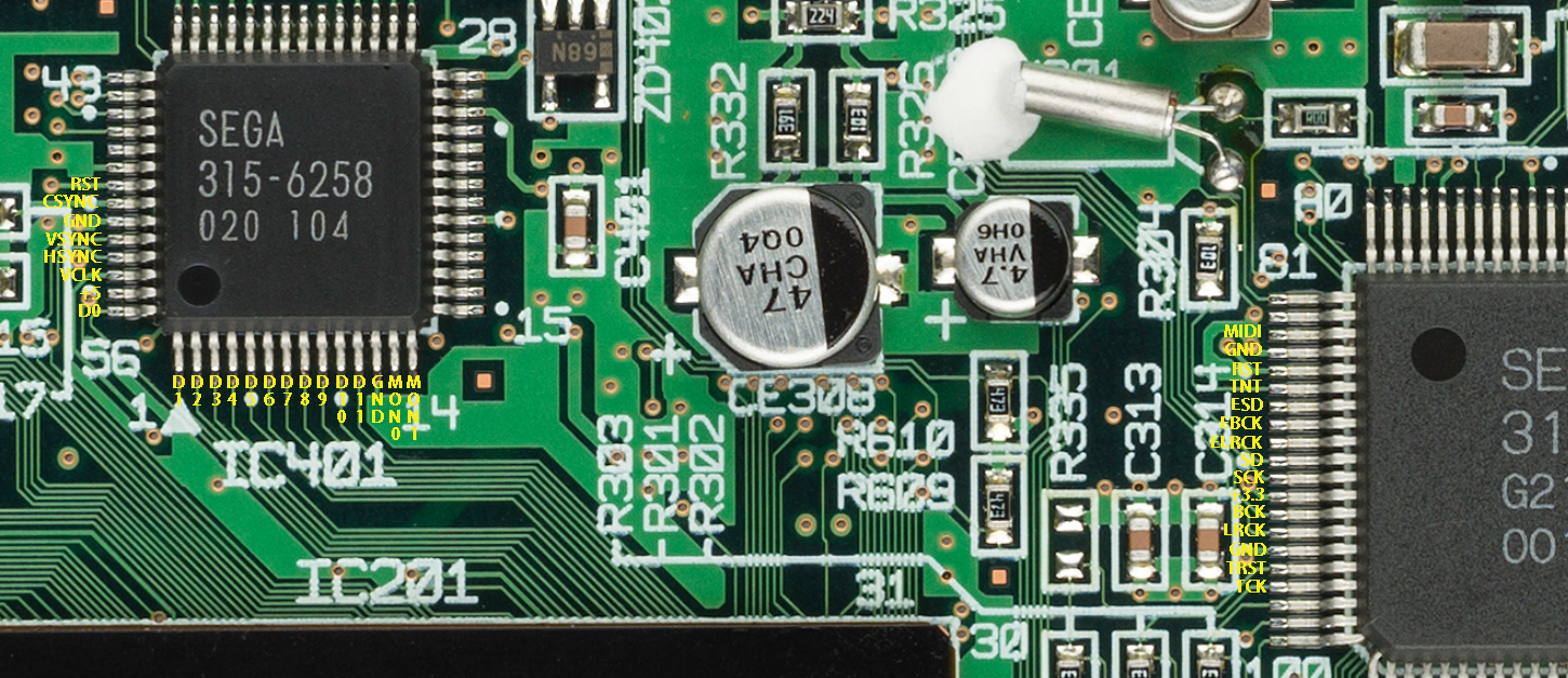
Check for shorts with a multimeter, there should be no adjacent pins connected *Refer to the image below, for a pinmap. (Not all pins hooked up on flex cable are used)
Step 4 - Soldering the controller flex
Click to expand/collapse
Place the controller flex as shown and solder on R601 & R602
Gently bend the flex and solder as shown below
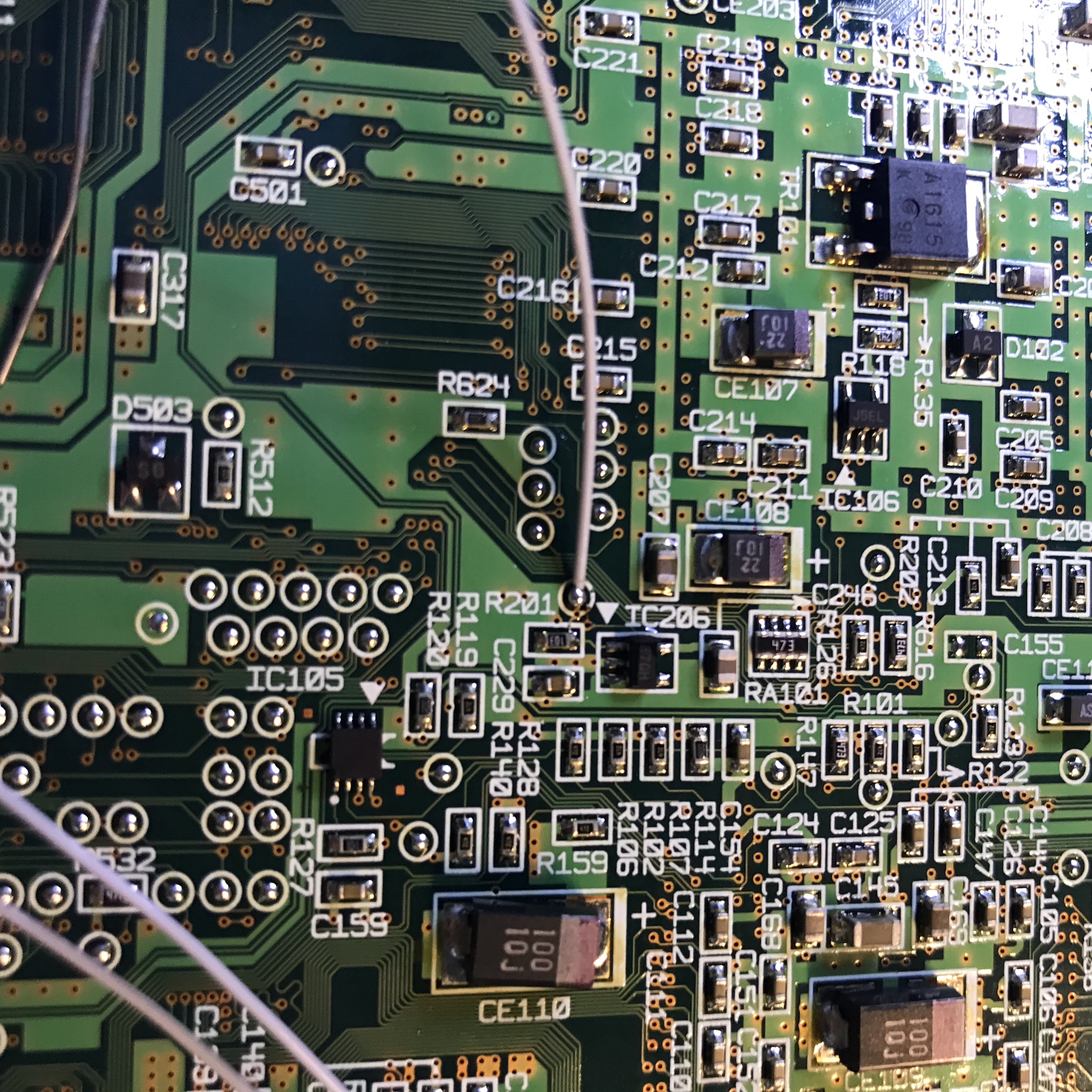
If you do not wish to use the flex and run wires instead the hooksup are as shown.
R601 Goes to P1 and R602 to P2:
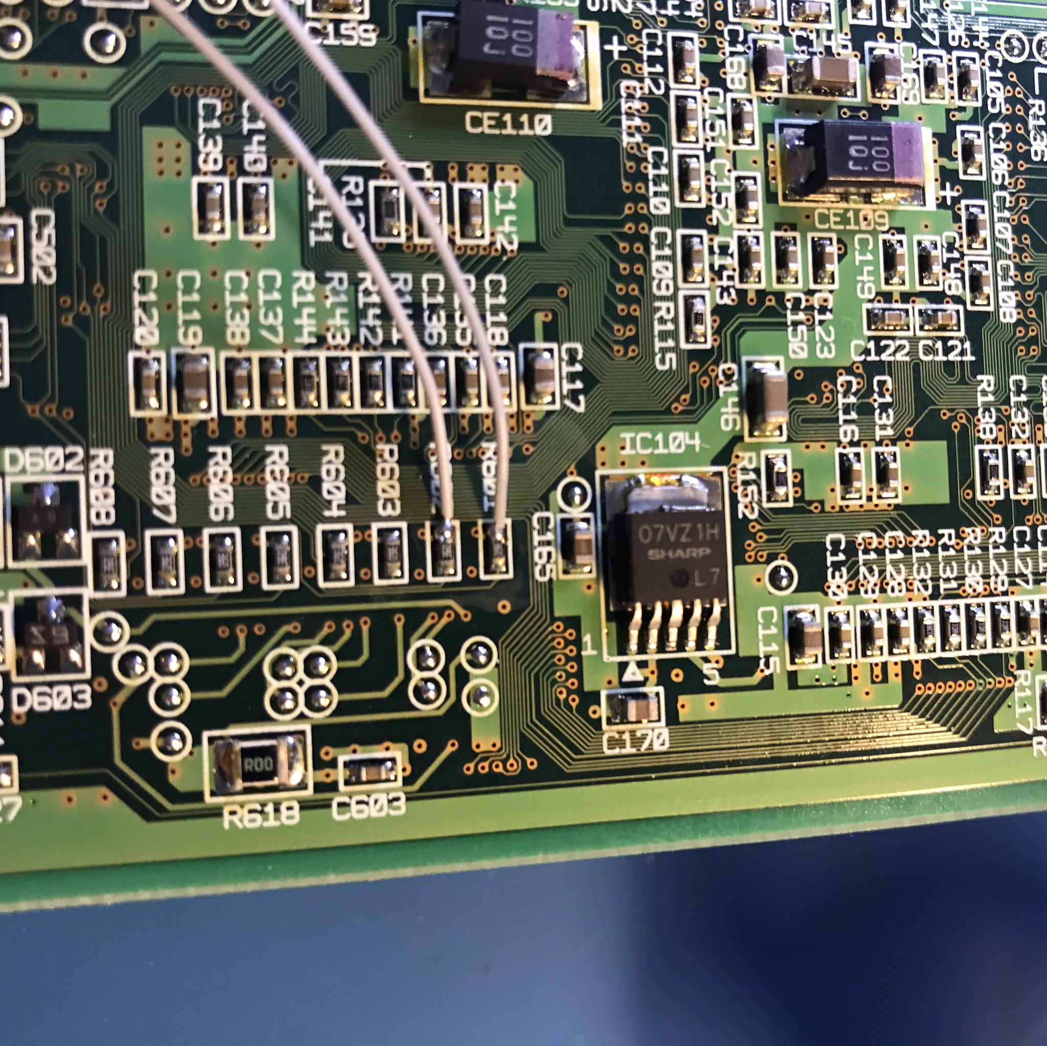
RST goes to this pin:
Step 5 - Reinstalling the motherboard and finishing up
Click to expand/collapse
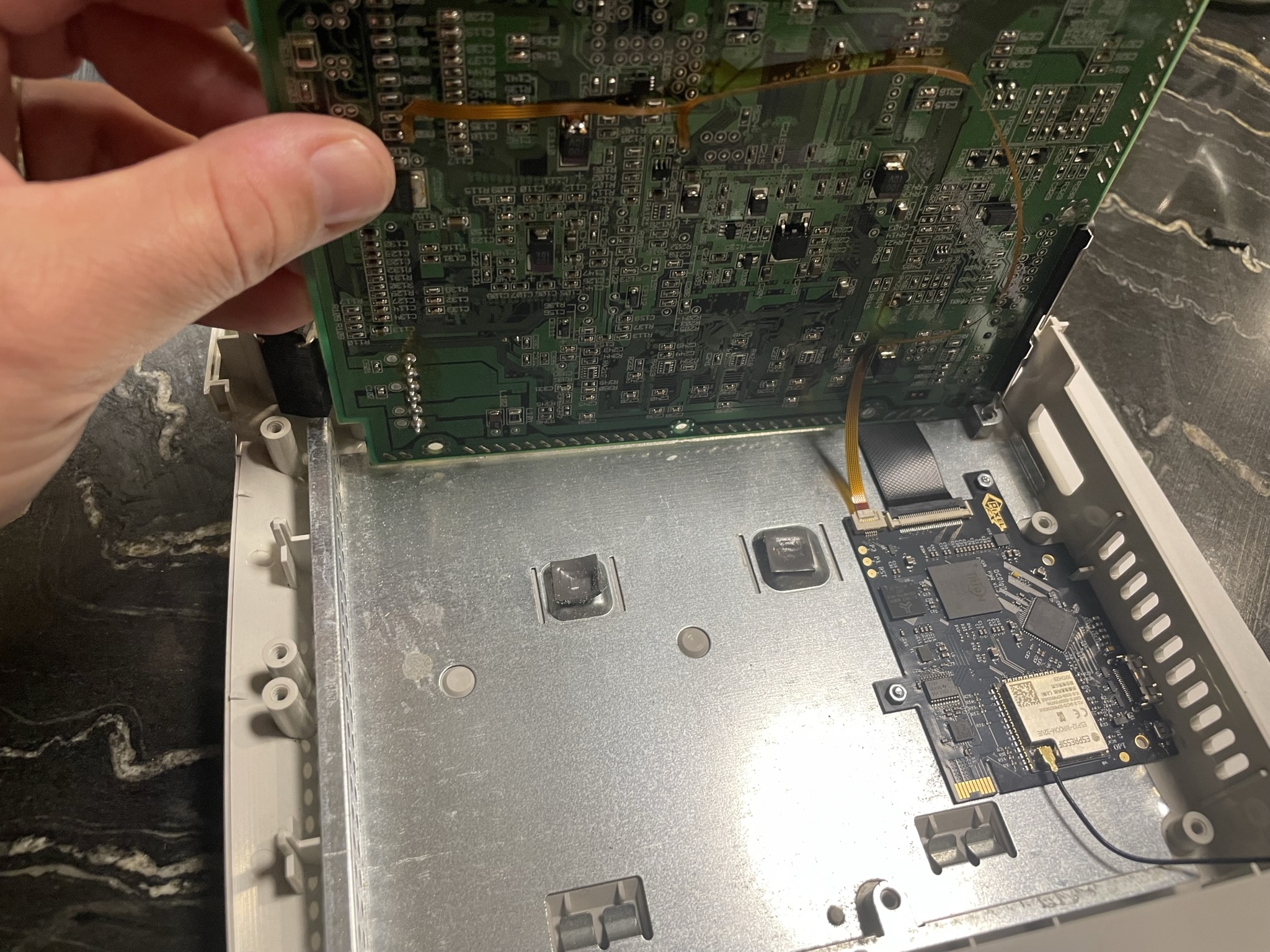
Align the motherboard in this way and use the flip lock connectors to insert both FFC cables. After latching the FFC cables gently lay the motherboard back into place and reassemble the console.
Step 6 - First Bootup
Click to expand/collapse
- Make sure you have the fan hooked up and a disc drive plugged in. Without these items plugged in the DC may emit a black screen.
- The DCDigital is set up by default to scale a 480i input image. This is so RCA composite cables can be used to test the installation. Remember to change to FORCE VGA in the DCDigital OSD.
Congratulations! Enjoy the DCDigital and we appreciate your support.